Mission Specialist defender Operator's Manual

|
|
MSS Defender Operator's Manual, 1.00.00 |
Click on the model you would like to view...
   Most Popular Topics |
|
|
MSS Defender Operator's Manual, 1.00.00 |
Copyright NoticeThis material is copyright protected. No material may be reproduced or transmitted in any form or by any means for any purpose without expressed written consent of VideoRay LLC. Copyright © 2022, VideoRay LLC - The Global Leader in Micro-ROV Technology |
|
|
MSS Defender Operator's Manual, 1.00.00 |
Language Support
|
|
|
MSS Defender Operator's Manual, 1.00.00 |
Table of Contents
|
|
|
MSS Defender Operator's Manual, 1.00.00 |
About this DocumentDocument NavigationYou can navigate through the documentation to specific topics using the menu, or step through sequentially using the Next and Previous arrowhead buttons. The Next button will step you from the current topic to the next topic at the same level unless the current topic has a sub-topic. If the current topic has a sub-topic, the Next button will step you into the first sub-topic. The Previous button works similarly, but in reverse sequence. Your current location within the document is shown as a "breadcrumb" trail at the top of each page under the document title. You can click on any level of the breadcrumb hierarchy to go that location. You can also use the following keyboard shortcuts:
Links are shown in brown font. Finding InformationThis document includes a Table of Contents, Glossary / Index and Google search on each page. You must be connected to the Internet in order to be able to use the Google search, and you can select whether to search VideoRay's online document library only (the default) or the Internet. Document ConventionsSeveral symbols are used throughout this documentation to add emphasis and to assist in relocating important information. The following table describes these symbols and their uses.
Document Customization - My_Notes
Beyond this DocumentThere is no substitute for experience and/or training, especially with respect to the real purpose for which you plan to use this equipment. We encourage you to explore options beyond the scope of these materials to expand your knowledge and skills necessary to support your applications. In addition to this documentation, VideoRay offers training and technical support and hosts a general user discussion forum and user image gallery. We also realize that collectively, users of our products spend considerably more time operating our systems than we do ourselves. Users also encounter more diverse operating environments across an extremely broad range of applications. We highly value this vast experience base, and invite and encourage you to share your experiences and suggestions with us. Please feel free to contact us by any of the methods listed below. Quality CommitmentVideoRay strives to design, manufacture, deliver and support the highest quality products and services, including this documentation. We have made every effort to ensure that this documentation is accurate and provides you with the most up-to-date information. If you find any errors in this documentation or have suggestions for improvements, each page contains a "Help us improve this document" feedback link in the left margin (you must be connected to the Internet to use this link).
DisclaimerThis document is deemed accurate at the time of its writing, however it is not a legal contract and the information contained herein should not be construed to represent any form of commitment. This document as well as the associated products and services are subject to change without notice. Alternate FormatsSingle HTML Page Format Portable / Printable Format HTML File Set |
Customize this Documentation - My_NotesMy_Notes are easy to incorporate directly into the pages of this manual. They can be used to clarify content, add additional information, or document your custom settings, operational tactics or procedures. My_Notes are page specific and display at the bottom of the desired page under the "My_Notes" heading. No programming is required - it is as simple as saving a file with your notes. Creating My_NotesMy_Notes can be written in HTML or plain text. HTML allows for more flexible formatting and inclusion of images or links to other web pages. To add a My_Note, create an HTML or text file containing the note and save it in the VideoRay\My_Notes\ folder, which can be found in the computer account user's documents folder (Documents\ for Windows 7, or My Documents\ for Windows XP). The file should be named the same as the page in which you want the note to appear, with a "my_" prefix (without the quotes). For example, if you want a My_Note to appear at the bottom of this page, the name of the file to create is: my_custom_my_notes.html. The name of the page being viewed can be found in the address bar of the browser being used to display this documentation.
Viewing My_NotesWhen you reload the page, your My_Note will appear - there is nothing else to install or configure. A sample My_Note file has been included to display the My_Note below. You can use this file as a model for creating your own My_Notes. Updating My_NotesTo update a My_Note, simply edit and re-save the My_Note file. Removing My_NotesMy_Notes can be removed by deleting or renaming the My_Note file. Sizing My_Notes Display (Optional)The default vertical size for My_Notes is set to 200 pixels, which is used for the sample My_Note below. Due to browser limitations, My-Notes do not size dynamically. This means that a long My_Note may display a scroll bar in order to view the whole My-Note. You can adjust the size to eliminate the need for the scroll bar. To set the size of a My_Note, you need to edit the file named "my_notes_size_table.js" in the My_Notes\ folder (location defined above). The file contains one line for each page of this document using the following format: window.page_name = size_in_pixels; Find the line for the page that includes the My_Note you want to resize and replace the value of size_in_pixels with the desired size in pixels. The page names are listed alphabetically. Example line from the "my_notes_size_table.js" file for this page: window.custom_my_notes = 200;
|
|
|
MSS Defender Operator's Manual, 1.00.00 |
How to Get HelpHelp for your MSS Defender All Hours Self-Service / Crowd-Source Tools
Global Support
Regional Support
Training
Operational Strategies and Tactics SupportIf you need help understanding how to apply your system to a specific project, contact VideoRay or you local VideoRay dealer. We can provide guidance or help you find a certified consultant. |
Before Contacting SupportPlease make sure to consider the following information before contacting VideoRay's Technical Support to report a problem. The following information should available:
Once you have collected the recommended information, visit the "How to Get Help" page for contact information. In addition, please review VideoRay's Support website for additional information about:
|
|
|
MSS Defender Operator's Manual, 1.00.00 |
MSS Defender |
|
|
MSS Defender Operator's Manual, 1.00.00 |
Mission Specialist Vehicle ConfigurationsMission Specialist vehicle configurations include:
The Defender system is designed to use multiple different topside control architectures for different operational needs. See the Operator Control Consoles section for more information about the available topside configurations. Vehicles are shown approximately to scale. |
|
|
MSS Defender Operator's Manual, 1.00.00 |
Quick Start InstructionsThese Quick Start Instructions are streamlined to cover just the essentials of operating your MSS Defender
The following Quick Reference Sheets are available for the VideoRay Defender: Topics in this Section |
Safety First
How Safe Is Safe Enough?Addressing all aspects of safety while working in a water environment is beyond the scope of this documentation. VideoRay encourages you to participate in safety training appropriate for your industry and applications, including such topics as vessel operations, first aid, survival and other relevant topics. |
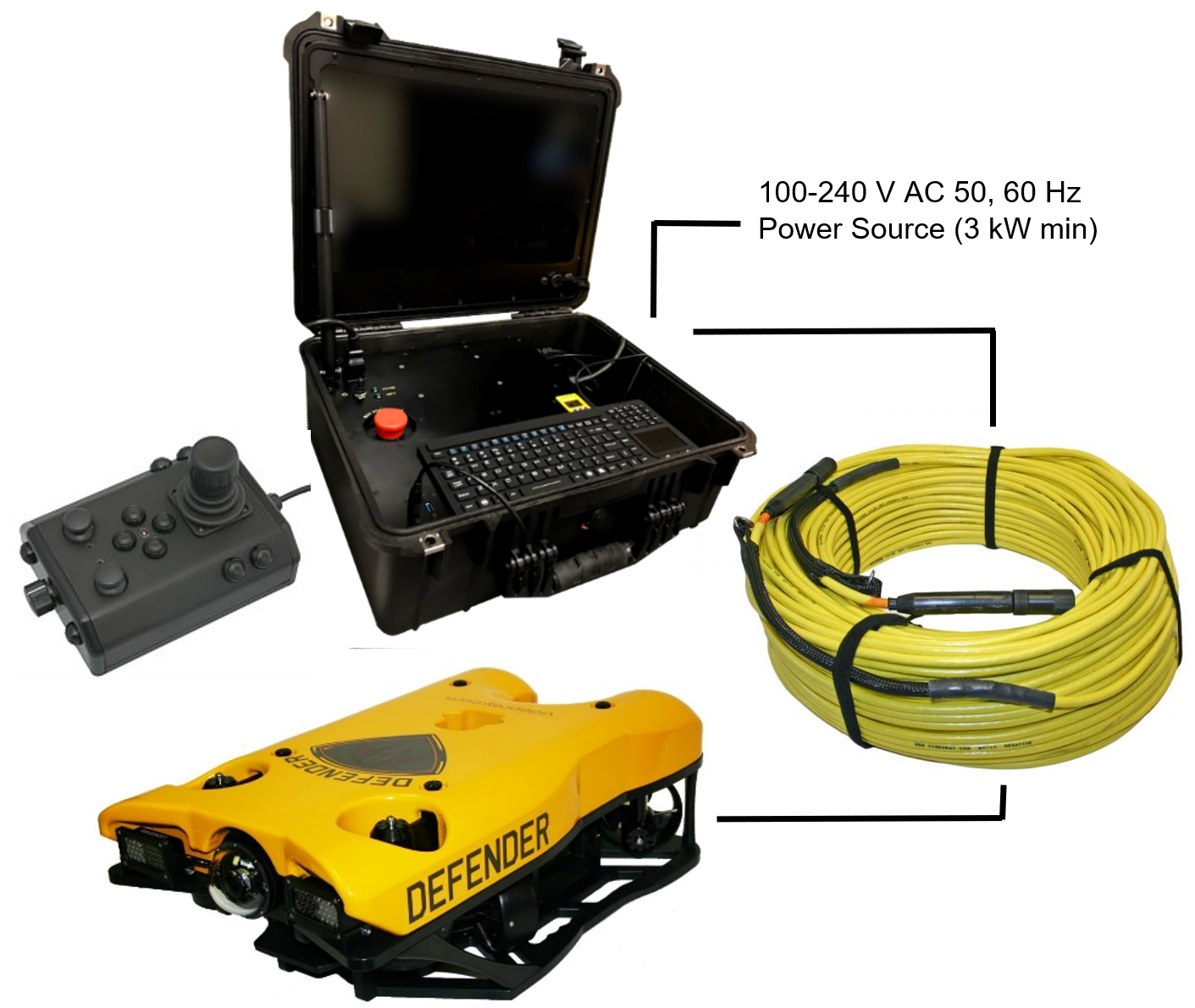
Introduction to the System ComponentsUnpack the system and familiarize yourself with the components.
Additional ItemsAdditional items may be supplied with your system including tools, spare parts and other items. If included, these items are described in other sections of this documentation. Some items shown may be optional and not included with your configuration. |
Pre-Dive Preparations
The pre-dive preparations consist of five parts:
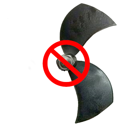
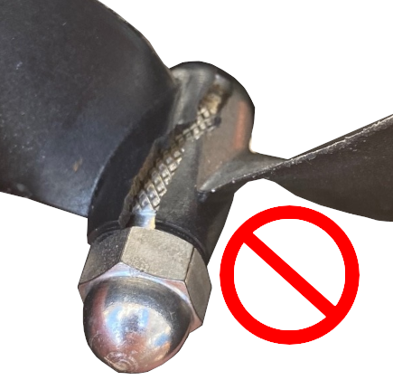
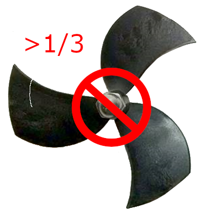
Conduct a Visual InspectionAssuming this is your first time using the VideoRay, everything should be in proper working order and ready to go, but it is good practice to perform a pre-dive inspection before every dive, even your first. If any problems are noticed, they should be addressed before continuing.
Make the ConnectionsIt is best to start making connections at the ROV and working your way to connecting the system to the power source.
Top View Side View Some of the cables have been connected at the factory. See the appropriate sections of the Equipment Guide for detailed information about each of the connections. You will typically need to connect only the ROV, tether, strain relief hand controller, and power cord.
Power On Tests
The VideoRay MSS includes two circuit safety components.
Testing the Circuit Safety ComponentsConnect the power cord to a suitable power source. The GFCI can be found inline in the power cord.
Power On and LIM TestsSet the Power switch to the On position. The green Power On indicator light should turn on. If the green Power On indicator light is not on, make sure the system is connected to a working power source and the GFCI switch is turned on. Twist the ROV Power switch to the On position. The green 400 V Power On indicator light should turn on. If the green 400 V Power On indicator light is not on, make sure the system is connected to a working power source and the GFCI and main power switches are turned on. Test the LIM. The LIM can be found on the right side of the Operator Control Console. The GFCI switch and the main and 400 V Power switches must both be set to On in order to perform this test.
Starting the VideoRay Control SoftwareMake sure the system is connected to a working power source and the GFCI / Circuit Breaker and Power switches are turned on.
See the Software Guide for more information about the VideoRay control software. Testing the System's FunctionsThe next step is to ensure that the essential features of the ROV are functioning properly. Use the hand controller to perform the following tests. The manipulator functions listed below do not necessarily represent the full capabilities of the system. See the Hand Controller section of the Equipment Guide for the complete list of functions and more information about using the hand controller.
Test the thrusters
Test the lights
Test the camera functions
Good AdviceThe time to catch small problems before they become big problems is during the pre-dive inspection. |
Dive OperationsAfter the previous four pre-dive checks and tests have been completed successfully, you are almost ready to commence the dive. But, there is one more issue to address that could affect the performance of the ROV. The ROV is designed to be operated in a near neutrally buoyant configuration, so the last step before launching your VideoRay is to check the buoyancy, and adjust the ballast if necessary. For most operations, the buoyancy is optimal when the top of the float block is even with the water surface and the ROV is level. If the ROV is too buoyant or too heavy, the vertical position may be hard to maintain or control.
Buoyancy Check and AdjustmentTo determine if the buoyancy is correct, lower the ROV and at least 3 meters (10 feet) of tether into the water. You can lower the ROV by the tether - it will not hurt the tether because there is Kevlar in it. Observe the ROV in the water - it should not be floating too high or sink. It should also be floating level and not tipped to one side or pitched up or down. If the ROV floats too high, you will need to add some ballast weights. If the ROV sinks, you will need to remove some ballast weights. If the ROV is not floating level, you can change the locations of the weights. The buoyancy can be adjusted by adding or removing the supplied ballast weights to the vehicle. The weights can be added to or removed from the slots by hand. For most operations, the weights should be evenly distributed to provide a balanced attitude of the ROV in water. Commence the DiveOnce the buoyancy has been adjusted the ROV is ready to launch. Lower it into the water and operate the controls to maneuver it. The ROV can be lowered using the tether.
For your first dives, practice until you are comfortable operating the controls without looking at them and you are able to control the ROV with some precision.
Automated Flight OperationsAutomated flight operations require additional configuration and tuning to ensure accurate flight dynamics and control. See the Automated Flight Operations section for more details. Practice Makes PerfectDeveloping the skills to operate your MSS Defender |
Post-Dive OperationsAt the conclusion of your dive, retrieve the VideoRay and power down the system by closing VideoRay Balefire software, turning off the ROV power switch, shutting down the computer and then turning off the main power switch.. Make sure the ROV is secure before disconnecting the tether. After disconnecting the tether, keep the tether connectors clean and do not let them drag on the ground. Proper maintenance of your VideoRay system ensures a long service life and that it will be ready to operate when you are. After each dive, you should visually inspect the system for damage that might have occurred during your operation.
DebriefingCongratulations! You are well on your way to becoming an accomplished micro-ROV operator, but there are still many things to learn and skills to master. Continue learning about the system by reviewing the additional sections of this documentation and, most importantly, practice, practice, practice. If you encountered any difficulties or have any questions, review these Quick Start Instructions and the other documentation that came with your system, including the Equipment Guide. If you still have difficulty or questions, contact VideoRay. Your success is our success, and we are here to help you get the most out of your VideoRay.
Ready to Learn More?To accelerate your learning and receive recognition for your knowledge and skills, VideoRay offers in-person classes and online training as well as the Micro-ROV User Certificate program. Training can be delivered at your site and customized to your needs. To learn more about these opportunities, click on the training link above to visit the VideoRay Educational Resources website. |
|
|
MSS Defender Operator's Manual, 1.00.00 |
|
|
MSS Defender Operator's Manual, 1.00.00 |
FAQ (Frequently Asked Questions)New users typically have some basic questions about the MSS ROV Systems. Before getting to the details, this section is provided to address the questions asked most frequently, without having to scan through the manual to find the answers. If you have questions about a problem with a MSS ROV Systems, see the Diagnostics and Repair section of the Maintenance Guide for more information.
More Questions?Additional questions and answers are available online at www.rovfaq.com, which is also linked at the bottom of each page. The online FAQ is updated regularly. |
|
|
MSS Defender Operator's Manual, 1.00.00 |
RequirementsThe VideoRay Mission Specialist Defender requires an external power source capable of producing 100 - 240 V DC; 50, 60 Hz output with a minimum steady-state capacity of 3,000 Watts. The Defender ROV weighs approximately 20 kg (45 pounds) in its case. The ability to lift at least that much weight is required to transport and deploy the ROV. Using trained operators and technicians is highly recommended. |
SpecificationsSpecifications for the VideoRay Mission Specialist Defender are provided on the following pages.
Product NewsSee www.videoray.com for the most up-to-date product information. |
Specifications for the ROV ModulesSpecifications for the VideoRay M5 Modules are provided on the following pages. |
Power Module SpecificationsDepth Rating
Mechanical
Connections
Power Input
Power Output
|
Communications Module SpecificationsDepth Rating
Mechanical
Connections
Power Input
Power Output
Communications
Sensor Feedback
M5 Communications Module features and specifications are subject to change without notice. |
AHRS Module SpecificationsDepth Rating
Mechanical
Connections Power Input
Communications
Sensor Feedback
IMU Features
M5 AHRS Module features and specifications are subject to change without notice. |
Thruster Module SpecificationsDepth Rating
Mechanical
Connections
Power Input
Communications
Sensor Feedback
Features
M5 Thruster Module features and specifications are subject to change without notice. |
Camera Module SpecificationsDepth Rating
Mechanical
Connections Power Input
Communications
Sensor Feedback
Protocols
Visibility Features
M5 HD Camera Module features and specifications are subject to change without notice. |
LED Light Module SpecificationsDepth Rating
Mechanical
Connections
Power Input
Communications
Sensor Feedback
Features
M5 LED Light Module features and specifications are subject to change without notice. |
Specifications for the ROV AccessoriesSpecifications for the VideoRay Mission Specialist Defender accessories can be found on the respective information pages of each accessory. See the Optional Accessories section for more information. |
Tether SpecificationsTether Diameter
New tether was introduced in 2018. These tethers include a braided Kevlar around the conductors, are slightly different diameter and can be identified by an "FB" code printed on the tether.
Minimum Tether Bend Radius
Tether Connector Pin Configuration
Tether pin numbering in the connector is shown above. When looking at the mating surface of the connector, Pin 1 is the offset pin / socket. For male connectors, pins 2-8 proceed in a clockwise direction. For female connectors, sockets 2-8 proceed in a counter-clockwise direction. Tether Pin Function and Conductor Wire Gauge
Tether BuoyancyPerformance and Neutral tether includes buoyancy compensating foam that provides near neutral buoyancy in fresh water. Negative tether contains no foam and will sink. The connectors do not contain any buoyancy compensation and will sink slightly. Tether StrengthAll tether types include Kevlar that is rated at 450 kg (1,000 pounds), the connectors are rated 80 kg (175 pounds). The maximum usable tether length is limited by the ability of the tether to transmit power and data signals. The maximum usable tether length of MSS systems is about 550 meters (1,800 feet). MSS systems can use fiber tether to extend the range. See the Tether Management section of the Operations Guide for more information. Kevlar is a registered trademark of E. I. du Pont de Nemours and Company |
|
|
MSS Defender Operator's Manual, 1.00.00 |
System Voltage AdvisoryAC InputInput voltage is universal at 100-240 VAC; 50, 60 Hz. The power requirement for the Mission Specialist operating at full power settings is 3,000 Watts. A 2,000 Watt source (i.e. generator) can be used if the system will not be used at full power settings. ROV DC PowerHistorically, the tether voltage to power the ROV has been increasing. Economy models (including the Scout, Explorer and Voyager), Pro 3 variants and the Pro 4 Ultra use 48 V DC for vehicle power. The Pro 4 uses 74 V DC. Mission Specialist systems uses 400 V DC with plans to use higher voltages in the future. Systems with voltages higher than 48 V DC include a LIM (Line Insulation Monitor) protection module in the ROV DC circuit.
VideoRay Negative, Neutral and PPT tethers are rated to 600 V DC and are safe to use on any system through the Mission Specialist 400 V DC.
The new version of the extended TDS is available that includes a 600 V rated slip ring. If you have any questions about system voltage and compatibility, contact VideoRay Support. |
|
|
MSS Defender Operator's Manual, 1.00.00 |
Equipment GuideUnderstanding the features and capabilities of the Mission Specialist equipment is essential to get the most value out of using the system. The sections within this Equipment Guide provide details about each of the components. Topics in this Section |
|
|
MSS Defender Operator's Manual, 1.00.00 |
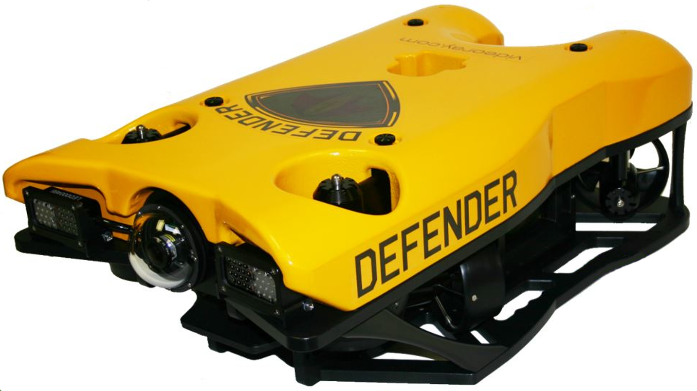
ROVThe Mission Specialist ROV consists of modular components (thrusters, lights, cameras, sensors) and a custom frame. Each Mission Specialist vehicle is designed to meet the requirements of a specific underwater mission. The frame and sensor payload can be optimized to deliver the vehicle to its intended destination and accomplish the tasks, whether that be recording video, taking measurements of various parameters, or navigation and remote sensing such as sonar or laser imaging.
The sections that follow provide information about the frame and modular components. |
ROV NomenclatureROV nomenclature follows the general pattern for seagoing vessels. The image below provides a visual reference for the directions and attitude relative to the ROV. 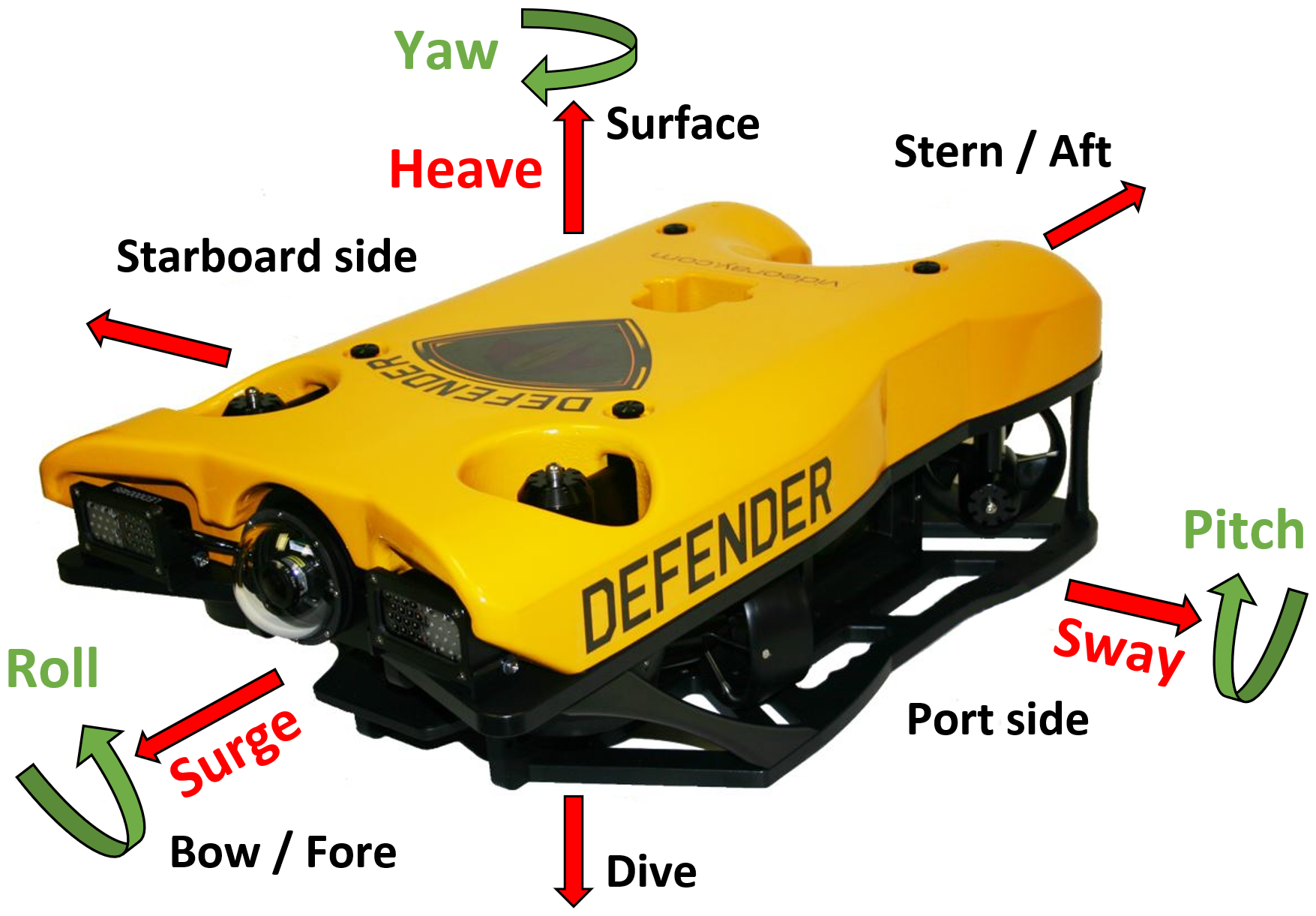 ROV Orientation and Directions ReferenceBow - The front of the ROV. Stern - The rear of the ROV Port - The left side of the ROV when facing forward. Starboard - The right side of the ROV when facing forward. Fore - Towards the front or The forward direction. Aft - Towards the rear of the rearward direction. Surface - To ascend or move up in the water column to a shallower depth. Dive - To descend or move down in the water column to a deeper depth. ROV Attitude and Motion ReferenceSurge - Forward and Reverse motion of the ROV, forward is positive. Heave - Up and Down motion of the ROV, up is positive. Sway - Left (to port) and Right (to starboard) lateral motion of the ROV, left is positive. Yaw - Right (to starboard) and Left (to port) rotational motion of the ROV, right (clockwise, viewed from the top) is positive. Pitch - Bow Up or Bow Down inclination of the ROV, bow up (clockwise, viewed from the port side) is positive. Roll - Port UP or Port Down relative to Starboard, port up (clockwise, viewed from the rear) is positive. defender |
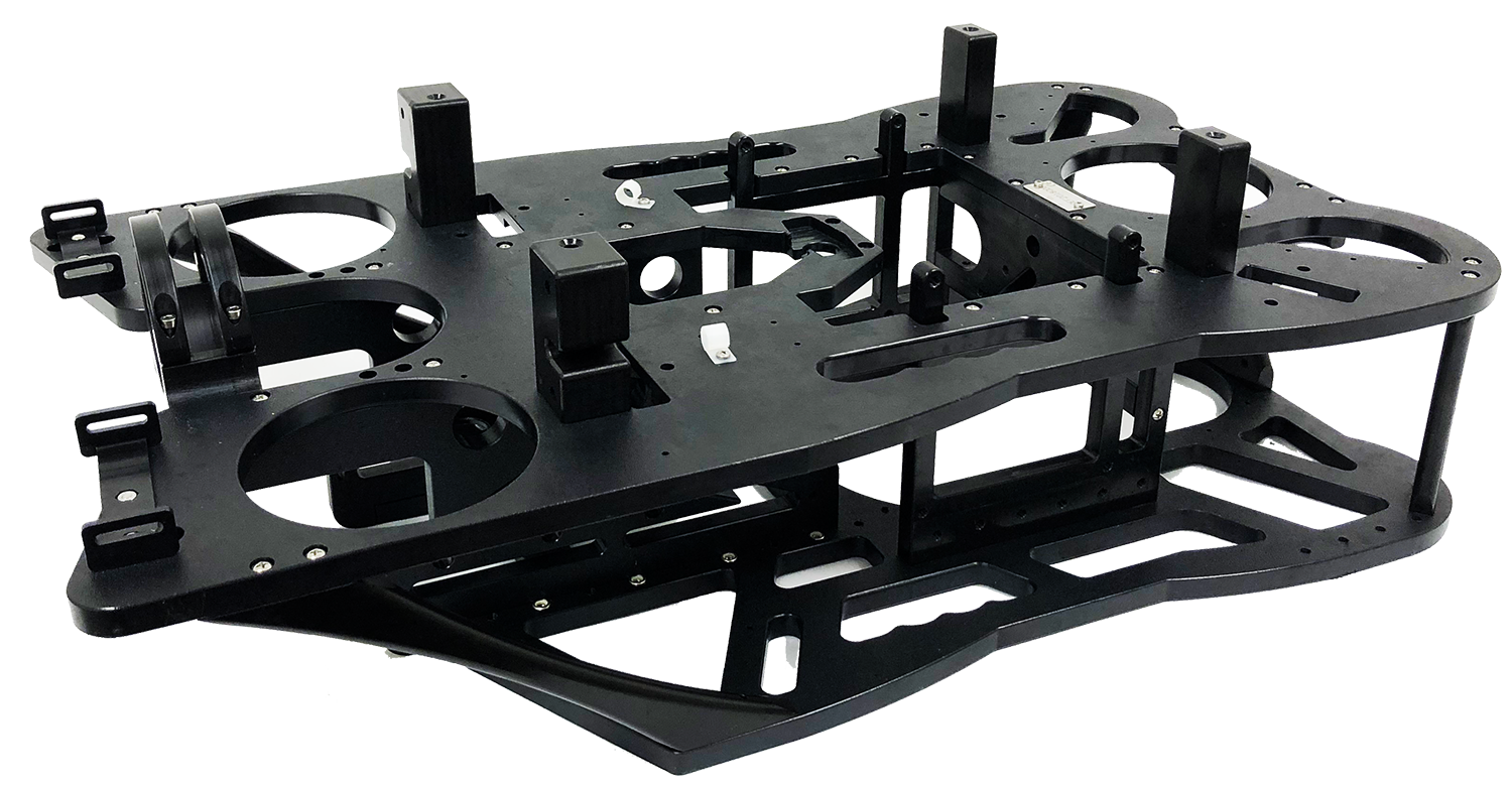
Defender FrameThe Mission Specialist frame provides the structure to combine the modular components and accessory payload. The modular concept allows the Mission Specialist frame to be optimized for the specific tasks for which the vehicle is designed. Each vehicle frame can be optimized for specific applications.
The Defender Frame is a 4 vectored horizontal thrusters x 3 vertical thrusters. It uses two vertical thrusters in the front and one in the rear. It is designed to carry a complement of accessories including sonar, manipulator and DVL. Other accessories would require a payload mounting platform configured for each accessory.
|
Defender Dimensioned Views |
Defender Exploded Views |
Defender Buoyancy
The Mission Specialist buoyancy consists of a top float block made of buoyant material. The purpose of the float block is to offset the weight of the vehicle structure and modules to achieve a neutral buoyancy. The float block is usually designed with extra flotation capacity to allow accessories to be mounted to the vehicle. Ballast weights are then added to fine tune the buoyancy depending on the payload and whether the ROV will be used in fresh or salt water. The Defender float block is secured to the vehicle using 4 screws. It can be removed to access modules and connections. |
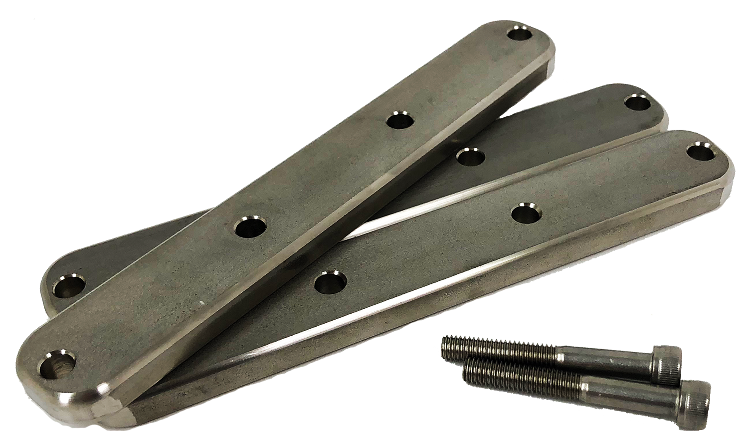
Defender BallastThe Mission Specialist Vehicle's buoyancy can affect performance and should be adjusted for water type (fresh versus salt), payload and performance requirements.
The Defender ballast configuration consists of stainless steel weights that can be attached to the frame using the screws provided. Ballast should be added until the vehicle has a slight positive buoyancy so that it will return to the surface slowly when pushed down manually. There are numerous hole in the ballast and mounting holes that allow the ballast to be placed slightly fore or aft to trim the vehicle so that it is level. The Defender has pitch control, so a perfectly level trim is not necessary. If the mission calls for pitch down (retrieving object from the bottom) or pitch up (ship's hull inspection), adjusting the trim accordingly can help reduce the pitch control effort required.
|
Power ModuleThe Power Module receives power from the topside and converts it to power levels required by the various modules, sensors and accessories.
8 Pin Male Tether Connector
5 Pin Female High Power (Thruster, Lights) Connector (2)
Power is rated at 750 Watts per port for 1,500 Watts total. 9 Pin Female Communications Module Interface Connector
Power is rated at 300 Watts for the 24 Volt circuit and 120 Watts for the 12 Volt circuit. Power Module ArrangementThe Defender vehicle power module is configured as follows:
|
AHRS ModuleAHRS - Attitude and Heading Reference System The AHRS is also sometimes referred to as an Inertial Measurement Unit, or IMU. It provides feedback on the vehicle's orientation. Measurements include magnetic heading, attitude and rates of change. The AHRS also includes a pressure sensor to determine the depth of the vehicle.
Cable Pinout
|
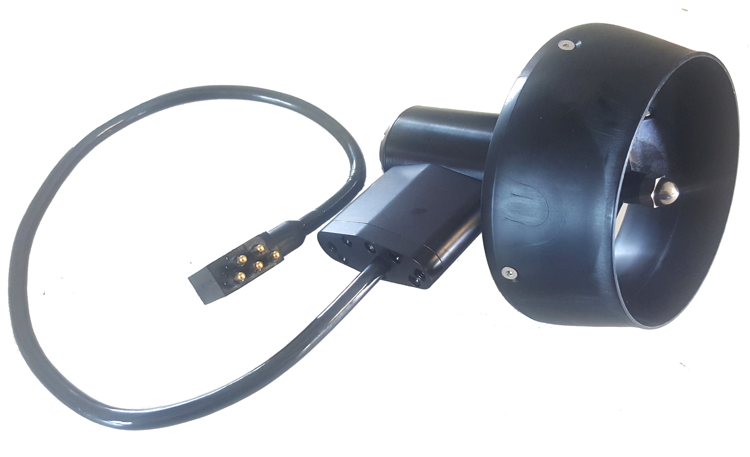
Thruster ModuleMission Specialist vehicles use a modular thruster configuration that allows vehicle designs to be optimized for water conditions and payload delivery requirements. Modular thrusters are also easy to replace in the field.
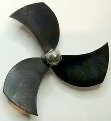
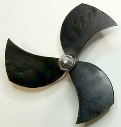
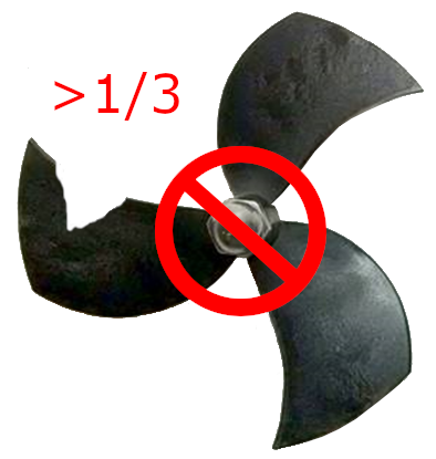
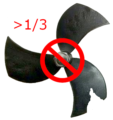
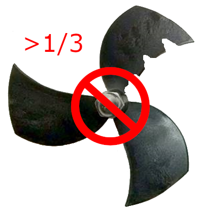
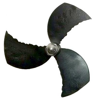
Thruster PropellerThe propellers are designed to be used on counter-rotating thruster arrangements to eliminate torque roll or yaw. Propellers are identified by their pitch orientation using left and right based on their pitch. The convex edge of the propeller blade is the leading edge during motion that is considered forward for that thruster.
Cable PinoutThe Thruster connector uses a male / female stackable connector allowing the thrusters and LED lights to be connected in series.
The Defender vehicle is a Defender frame that uses a vectored horizontal thruster arrangement, and three vertical thrusters. The thrusters are configured as shown below:
|
Camera ModuleThe camera module provides a live video feed from the vehicle to the surface.
Cable Pinout
High Definition Camera
|
LED Light ModuleThe LED Light Module provides variable levels of illumination and beam pattern control.
Cable PinoutThe LED Light connector uses a male / female stackable connector allowing the LED lights and thrusters to be connected in series.
|
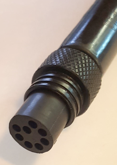
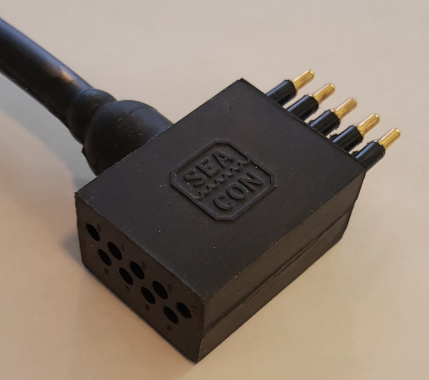
ROV ConnectionsThe Mission Specialist ROV system uses 3 types of connectors for power and communications between the control panel, vehicle modules and accessories. 8 Pin Tether Connector
Pin numbering starts at 1 for the offset pin and is clockwise on the male connector and counter clockwise on the female connector. 5 Pin Thrusters and Lights Connector
Pin numbering is clockwise starting at 1 in the upper left when looking at the face of the male connector with the row of 3 pins on top. 9 Pin Accessory Connector
Pin numbering is clockwise starting at 1 in the upper left when looking at the face of the male connector with the row of 5 pins on top. ROV Connections |
|
|
MSS Defender Operator's Manual, 1.00.00 |
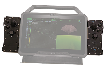
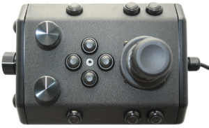
Operator Control ConsolesThe Operator Control Console is available in several configurations. Each configuration is compatible with the ROV, tether and accessories, and can be used interchangeably. The configurations are: Expeditionary Splashproof Controller
The Expeditionary Splashproof Controller is IP65 rated, lightweight and has the smallest footprint for excellent portability and stealthiness. It also includes dedicated side pods that serve as the hand controller.
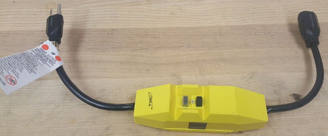
Workhorse Splashproof Control Console
The Workhorse Splashproof Control Console, is IP65 rated for all weather use. It requires topside power, either shore power, generator or battery and inverter.
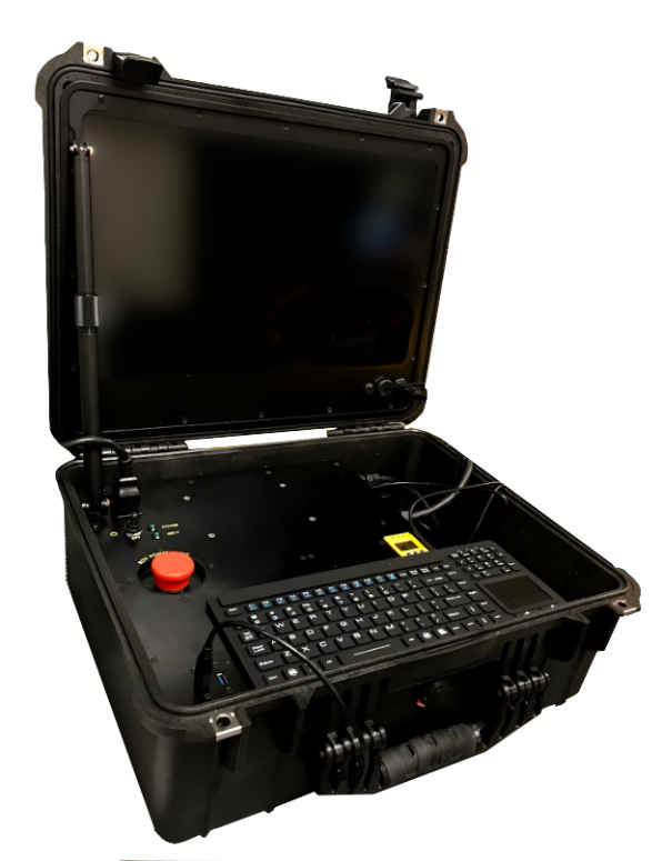
Workhorse Control Console
The Workhorse Control Console is similar to the Workhorse Splashproof Control Console, but it is not rated for all weather use and requires some shelter for the controller when used in inclement weather. It includes an embedded processor unit. It requires topside power, either shore power, generator or battery and inverter.
Power Source OptionsIn addition to control console configuration, different methods of powering the ROV are available. See the Power Source Options page for more information. |
Expeditionary Splashproof ControllerThe Expeditionary Splashproof Controller is a VideoRay custom tablet, frame and side-mounted hand controller pods. It is designed for compact, all weather use and convenience for the operator.
The Expeditionary Splashproof Controller is designed to be used as a stand-alone topside control console with the ROV on-board batteries and fiber tether/reel, or it can also be used in conjunction with the Workhorse Splashproof Control Console, which provides topside power for the ROV for continuous operations. Setting Up the ControllerController UseThere are several ways to operate the controller. It can be placed on a working surface flat or using the attached kick-stand on the rear. It can also be hand-held, with or without the included neck strap. When used with the Workhorse Splashproof control console, it can be mounted on the bracket in the lid of the console. This image shows the mounting plate for use with the Workhorse Splashproof control console and kick-stand.
Hand Controller CompatibilityThe Expeditionary Splashproof Controller can be used with the integral side pods, or any other VideoRay Controller, including the IP65 hand controller or the Xbox Elite hand controller. When using with an external controller, the side pods should be removed. OperationTo start the Expeditionary Splashproof Controller, press the power button on the right-hand side. Launch the ROV operating Greensea workspace software using the Defender icon on the desktop for your version of the Greensea Workspace. To stop the system, first close the software, then select the system icon in the upper left and choose shut down
ChargingThe Expeditionary Splashproof Controller is battery powered. It has a standard wall adapter, but can also receive charge through the connection cable to the reel or Workhorse Splashproof control console. |
Expeditionary Splashproof Controller Safety CircuitsWhen used with the ROV On-Board batteries, the Expeditionary Splashproof controller does not require any safety circuits. Shore or grid power is required to charge the tablet computer and the ROV On-Board batteries. When possible is it best to do this using GFCI protected outlets. |
Expeditionary Splashproof Switches and ConnectionsThe current Expeditionary Splashproof computer is the Dell Latitude Rugged Extreme Tablet. For more information about the tablet, consult Dell's 7220 Supporting Documentation. The following features, switches and connections can be found on the Expeditionary Splashproof Controller:Front
Right Side
Bottom
Back
The back of the tablet / docking station includes the mounting bracket and kick-stand. |
Workhorse Splashproof Operator Control ConsoleThe Workhorse Splashproof Control Console consists of the Expeditionary Splashproof Controller, which is the control processor and Human Machine Interface (HMI), and the Workhorse Splashproof Control Console, which provides power and communications interfaces for the ROV.
These images are not to the same scale. Operator Control Console Power SpecificationsThe VideoRay MSS operates on typical residential power in the range of 100-240 Volts AC, 50,60 Hz. This can be provided from the land-based grid, a generator, or a battery with an inverter (optional). The typical power requirements for operating from a generator or inverter are 3,000 Watts continuous minimum. The system includes a GFCI (Ground Fault Circuit Interrupter) / Circuit Breaker to protect the operator. The power in the tether is 400 Volts DC. This circuit is protected by a LIM (Line Insulation Monitor). The procedures for testing the circuit safety components can be found in the Pre-Dive Preparations section of the Quick Start Instructions. The Expeditionary Splashproof Controller can be mounted on a bracket in the lid of the Workhorse Control Console or separated (the connection cable is required between the two in either configuration).Display Monitor Tilt ArmThe Display Monitor Tilt Arm on the left side of the Operator Control Console can be used to adjust the angle of the Operator Control Console lid and monitor. To adjust the angle of the monitor, loosen the locking collar, adjust the lid to the desired angle and tighten the locking collar. Make sure to loosen the display monitor tilt arm before closing the Operator Control Console lid, and be careful when closing the lid to avoid damaging the computer or monitor or pinching any cables. |
Safety CircuitsThe Operator Control Console includes three safety circuit components.
GFCI (Ground Fault Circuit Interrupter)The GFCI protects the operator from shock from the AC circuit of the power source. The GFCI is inline with the power cord. When initially connected to a power source, it is in the Off state. You must press the Reset Button to enable it. When enabled, the green LED will be illuminated.
LIM (Line Insulation Monitor)The LIM protects the operator and persons in the water nearby from shock from the DC circuit of the tether. While the GFCI switches are part of the GFCI component and must be turned on to operate the Operator Control Console, the LIM is automatically enabled when the system is turned on. The LIM operates on a principle similar to the GFCI and monitors the quality of the insulation of the conductors in the tether. If the resistance between the conductors drops below the safe threshold, the LIM will trip. A normal reading on the LIM display is > 4 M-Ohm, indicating that the insulation of the power conductors in the tether is good. If there is any degradation of insulation, the value displayed will decrease. The MSS LIM is two stage. When the LIM detects the resistance between the ROV power conductors falls below 900 kOhms, the yellow LIM Alarm A1 LED will turn on, but the power circuit will remain on. When the LIM detects the resistance falls below 200 kOhms, the yellow LIM Alarm A2 LED will turn on and the ROV power circuit will be disabled. The LIM can be reset by pressing and holding the R button. The yellow LIM Alarm light should turn off. To test the LIM, press and hold the T button. If the LIM continues to trip, the system should be inspected for a fault before being used. The LIM has additional features that are described in more detail in the LIM Module Manual. ROV Power Safety InterlockThe ROV Power Safety Interlock prevents the ROV power from being engaged unless an ROV is plugged into the tether. This feature protects users from accidentally contacting the ROV power circuit of an open tether connector. See the Operator Control Console Switches and Connections section for more information about these components and their locations, and see the Pre-Dive Preparations section of the Quick Start Instructions for information about testing these components. |
Workhorse Splashproof Switches and Connections
The Operator Control Console top includes the following switches:
The Operator Control Console top includes the following connections:
Mounting the Expeditionary Splashproof Controller in the Workhorse Splashproof Console LidThese images show the mounting plates on the Expeditionary Splashproof Controller and Workhorse Splashproof console. The Expeditionary Splashproof Controller is connected by engaging its mounting plate with the one in the console lid.
|
Computer |
Workhorse Operator Control ConsoleThe Operator Control Console provides power, communications and a video interface between the surface and the ROV through the tether. The computer, which runs software to control the ROV, is housed in the Operator Control Console along with a display monitor .
Operator Control Console Power SpecificationsThe VideoRay MSS operates on typical residential power in the range of 100-240 Volts AC, 50,60 Hz. This can be provided from the land-based grid, a generator, or a battery with an inverter (optional). The typical power requirements for operating from a generator or inverter are 3,000 Watts continuous minimum. The system includes a GFCI (Ground Fault Circuit Interrupter) / Circuit Breaker to protect the operator. The power in the tether is 400 Volts DC. This circuit is protected by a LIM (Line Insulation Monitor). The procedures for testing the circuit safety components can be found in the Pre-Dive Preparations section of the Quick Start Instructions.
Display Monitor Tilt ArmThe Display Monitor Tilt Arm on the left side of the Operator Control Console can be used to adjust the angle of the Operator Control Console lid and monitor. To adjust the angle of the monitor, loosen the locking collar, adjust the lid to the desired angle and tighten the locking collar.
|
Safety CircuitsThe Operator Control Console includes three safety circuit components.
GFCI (Ground Fault Circuit Interrupter)The GFCI protects the operator from shock from the AC circuit of the power source. The GFCI is inline with the power cord. When initially connected to a power source, it is in the Off state. You must press the Reset Button to enable it. When enabled, the green LED will be illuminated.
LIM (Line Insulation Monitor)The LIM protects the operator and persons in the water nearby from shock from the DC circuit of the tether. While the GFCI switches are part of the GFCI component and must be turned on to operate the Operator Control Console, the LIM is automatically enabled when the system is turned on. The LIM operates on a principle similar to the GFCI and monitors the quality of the insulation of the conductors in the tether. If the resistance between the conductors drops below the safe threshold, the LIM will trip. A normal reading on the LIM display is > 4 M-Ohm, indicating that the insulation of the power conductors in the tether is good. If there is any degradation of insulation, the value displayed will decrease. The MSS LIM is two stage. When the LIM detects the resistance between the ROV power conductors falls below 900 kOhms, the yellow LIM Alarm A1 LED will turn on, but the power circuit will remain on. When the LIM detects the resistance falls below 200 kOhms, the yellow LIM Alarm A2 LED will turn on and the ROV power circuit will be disabled. The LIM can be reset by pressing and holding the R button. The yellow LIM Alarm light should turn off. To test the LIM, press and hold the T button. If the LIM continues to trip, the system should be inspected for a fault before being used. The LIM has additional features that are described in more detail in the LIM Module Manual. ROV Power Safety InterlockThe ROV Power Safety Interlock prevents the ROV power from being engaged unless an ROV is plugged into the tether. This feature protects users from accidentally contacting the ROV power circuit of an open tether connector. See the Operator Control Console Switches and Connections section for more information about these components and their locations, and see the Pre-Dive Preparations section of the Quick Start Instructions for information about testing these components. |
Workhorse Switches and Connections
The Operator Control Console top includes the following switches:
The Operator Control Console top includes the following connections:
The Operator Control Console side includes the following switches:
The Operator Control Console side includes the following connections:
|
ComputerThe computer provides the hardware and operating system platform for VideoRay ROV control software and image and video editing and production. The computer is embedded in the Operator Control Console.
The computer includes the following connections (which are passed through to connectors on the Operator Control Console):
Additional SpecificationsOperating System
Temperature
Power Input
Hard Disk Space
|
HD Monitor
The monitor includes a brightness knob. The monitor includes the following connections:
Additional SpecificationsSize
Power Input
Native Resolution
Brightness
Features
|
Power OptionsEach Operator Control Console requires some sort of external topside power, and the Expeditionary Splashproof controller also requires the ROV On-Board Batteries when used in stand-alone mode. External Topside Power Requirement SpecificationsThe Expeditionary Splashproof Controller has its own internal battery and an external charger, like most laptops. The external charger requires 100-250 VAC, 50, 60Hz (typically plugged into a conventional 15 Amp, 120 VAC wall outlet in the United States. Other countries that use 240 V may have different amperage ratings for their residential outlets). The Workhorse Splashproof and Workhorse controllers require 100-250 VAC, 50, 60 Hz at a minimum of 3,000 Watts. (on 120 VAC supplies, this equates to 25 Amp, and on 240 VAC, 12.5 Amp). Power SourcesPower sources include the following:
|
PPS - Portable Power SupplyThe PSS has its own Operator's Manual. Please see its manual for more information. |
ROV On-Board BatteriesROV On-board Batteries provide power directly at the ROV. Communications from the topside are still required over fiber tether. |
|
|
MSS Defender Operator's Manual, 1.00.00 |
Hand ControllerThe hand controller is used to operate the VideoRay and its features. Several types of hand controllers are supported. Controllers not included in your configuration are available from VideoRay for purchase. Supported controllers include:
The hand controller functions are described in more detail in the following pages of this guide. Hand Controller CompatibilityAny Microsoft® Windows® compatible game controller can be used with the Mission Specialist, but each controller requires a configuration file to map the joystick, buttons and knobs to the ROV functions. Microsoft is a registered trademark of Microsoft. Windows is a registered trademark of Microsoft. |
VideoRay IP65 Controller
|
Forward / Reverse ControlThe joystick is used to control the forward / reverse motion of the ROV. Location
UseDisplace the joystick forward (away from you) to move the ROV forward. Displace the joystick rearward (toward you) to move the ROV backward. The greater the displacement from the center position, the faster the ROV will move or turn in that direction. The joystick can be moved in any direction to simultaneously move forward or backward while turning or moving laterally.
Forward / Reverse Control |
Lateral ControlThe joystick is used to control the lateral motion of the ROV. Location
UseDisplace the Joystick to the left to slide the ROV to its left. Displace the Joystick to the right to slide the ROV to its right. The greater the displacement from the center position, the faster it will move or turn in that direction. The joystick can be moved in any direction to simultaneously move laterally while moving forward/backward or turning.
|
Yaw ControlThe joystick is used to control the yaw motion of the ROV. Location
UseRotate the Joystick to the left to turn (yaw) the ROV to its left. Rotate the Joystick to the right to turn (yaw) the ROV to its right. Displace the Joystick to the left to slide the ROV to its left. Displace the Joystick to the right to slide the ROV to its right. The greater the displacement from the center position, the faster it will move or turn in that direction. The joystick can be moved in any direction to simultaneously turn while moving forward/backward or laterally.
Yaw Control |
Depth ControlThe Depth Control knob is used to make the ROV dive or surface by controlling the direction and amount of vertical thrust. Knob Location and Label
UseRotate the Depth Control knob forward (counterclockwise) to dive. The greater the rotation from the center position, the faster it will dive. Rotate the Depth Control knob backward (clockwise) to surface. The greater the rotation from the center position, the faster it will surface.
|
Pitch UpThe Pitch Up button increases the vertical angle of the vehicle in the upward direction. Button Locations and Labels
UsePress the Pitch Up button to pitch the nose of the vehicle up in 5 degree increments.
You can press the Pitch Down button to decrease the pitch, or press the Pitch Reset button to return to level. Pitch Up |
Pitch DownThe Pitch Down button increases the vertical angle of the vehicle in the downward direction. Button Locations and Labels
UsePress the Pitch Down button to pitch the nose of the vehicle down in 5 degree increments. You can press the Pitch Up button to increase the pitch, or press the Pitch Reset button to return to level. Pitch Down |
Pitch / Roll ResetThe Pitch / Roll Reset button restores the vehicle to a level attitude. Button Locations and Labels
UsePress the Pitch / Roll Reset button to restore the vehicle to a level attitude. You can press the Pitch Up button to increase the pitch, or press the Pitch Down button to decrease the pitch. Pitch / Roll Reset |
ReservedReserved |
Lights IntensityThe Lights knob controls the intensity of the lights. Control Location and Labels
UseRotate the Lights Intensity knob counter clockwise to dim the Lights and clockwise to increase the intensity of the lights.
Lights Intensity |
Camera Tilt UpThe Camera Tilt Up button increases the vertical angle of the front camera in the upward direction. Button Locations and Labels
UsePress and hold the Tilt Up button to tilt the front camera up. Release the button when the camera has tilted to the desired setting or has reached the end of its range.
Camera Tilt Up |
Camera Tilt DownThe Camera Tilt Up button increases the vertical angle of the front camera in the downward direction. Button Locations and Labels
UsePress and hold the Tilt Down button to tilt the front camera down. Release the button when the camera has tilted to the desired setting or has reached the end of its range.
Camera Tilt Down |
Camera Focus InThe Camera Focus In button adjusts the focus of the front camera for near objects. Button Location and Label
UsePress and hold the Camera Focus In button to adjust the camera focus for near objects. Release the button when the camera has focused to the desired setting or has reached the end of its range. Camera Focus In |
Camera Focus OutThe Camera Focus Out button adjusts the focus of the front camera for far objects. Button Location and Label
UsePress and hold the Camera Focus Out button to adjust the camera focus for far objects. Release the button when the camera has focused to the desired setting or has reached the end of its range. Camera Focus Out |
SnapshotThe Snapshot button saves a still image from the active camera. Button Location and Label
UsePress the Snapshot button to capture a still image from the active camera. Snapshots are saved as .JPG formatted files in the gss_logs folder. They are automatically named by date and time. For more information, see the Snapshots section of the Operations Guide.
|
Video RecordThe Video Record button toggles the video record feature for the active camera. Button Location and Label
UsePress the Video Record button to start recording a video from the active camera. Press the Video Record button again to stop recording a video from the active camera. When the recording is active, the record icon button is illuminated green. Video Recordings are saved as .MP4 formatted files in the gss_logs folder. They are automatically named by date and time. For more information, see the Video Recording section of the Operations Guide
|
Manipulator OpenThe Manipulator Open button opens the jaws of the manipulator. Button Locations and Labels
UsePress and hold the Manipulator Open button to open the jaws of the manipulator. Release the button when the manipulator jaws open the desired amount or have reached the end of their range.
Manipulator Open |
Manipulator CloseThe Manipulator Close button closes the jaws of the manipulator. Button Locations and Labels
UsePress and hold the Manipulator Close button to close the jaws of the manipulator. Release the button when the manipulator jaws close the desired amount or have reached the end of their range.
Manipulator Close |
Manipulator RotateThe Manipulator Rotate knob rotates the jaws of the manipulator. Button Locations and Labels
UseRotate the Manipulator Rotate knob clockwise to rotate the manipulator jaws clockwise (when viewed from the rear of the manipulator). Rotate the Manipulator Rotate knob counterclockwise to rotate the manipulator jaws counterclockwise (when viewed from the rear of the manipulator). Center the Manipulator Rotate knob to stop the manipulator jaws from rotating. Manipulator Rotate |
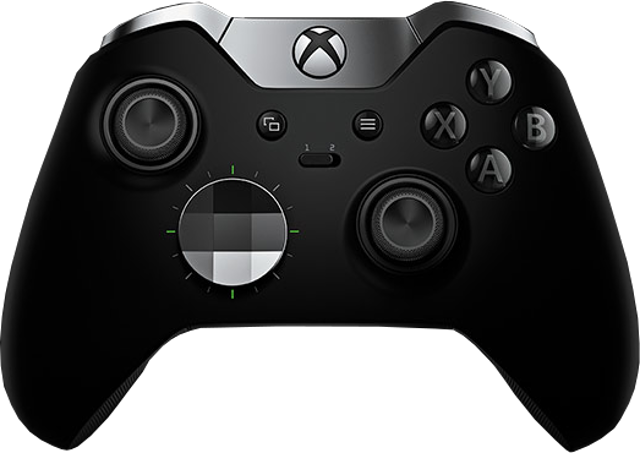
Microsoft Xbox Elite Controller
Hand Controller Connection
|
Common Controller Inputs
|
Pitch/Roll Mode
|
Sonar Mode
|
Camera/Lights Mode
|
Manipulator Mode
|
Raw Input
|
Expeditionary Side Pods Controller
Hand Controller ConnectionThe Expeditionary Controller Side Pods can be mounted and unmounted from the tablet frame. |
Top Controls
|
Bottom Controls
|
Unmounting and Mounting the Side Pods
Unmounting the Side PodsTo unmount a side pod, loosen the two thumb screws that hold the top of the pod to the back side of tablet frame and rotate the pod away from the frame at the top. Once rotated, the bottom catch can be released from the slot in the frame. Note, the thumb screws are retained in the pod.
Mounting the Side PodsThe pods mount using the reverse of the steps to unmount them. To mount a side pod, engage the bottom catch into the corresponding slot in the frame and rotate the top of the pod toward the frame. Once the pod is in place, secure the thumb screws into the back of the tablet frame. |
|
|
MSS Defender Operator's Manual, 1.00.00 |
Tether
Tether connects the ROV to the surface and provides power, communications, video and an APIC (Auxiliary Pair of Independent Conductors) for accessory use. The tether consists of conductors, a Kevlar® strength member, flotation (for Neutral and Performance tethers) and an outer jacket. It is available three types: Negative, Neutral and Performance (often called PPT), and can be purchased in standard and custom lengths. Neutral and Performance are neutrally buoyant in fresh water because they have a specially designed foam jacket. While larger conductors provide the best power transmission capacity, they lead to thicker tethers, which results in higher drag. Negative tether has the largest conductors (best power transmission capacity), followed by Neutral, and then Performance. Negative and Performance tether have the smallest diameter (least drag), while Neutral tether has the largest diameter. The tether connectors are wet mateable and can be connected while they are wet. One of the pins in the connector is offset. To connect the tether to the ROV, control panel or another tether, align the offset pin of the connectors and press the two connectors together until the base surface of each connector are touching each other. Then, connect the tether locking sleeves by screwing them together to secure the connection.Multiple tethers can be connected in series like conventional power extension cords. See the Tether Management section of the Operations Guide for recommended tether configurations.
|
Tether SpecificationsTether Diameter
New tether was introduced in 2018. These tethers include a braided Kevlar around the conductors, are slightly different diameter and can be identified by an "FB" code printed on the tether.
Minimum Tether Bend Radius
Tether Connector Pin Configuration
Tether pin numbering in the connector is shown above. When looking at the mating surface of the connector, Pin 1 is the offset pin / socket. For male connectors, pins 2-8 proceed in a clockwise direction. For female connectors, sockets 2-8 proceed in a counter-clockwise direction. Tether Pin Function and Conductor Wire Gauge
Tether BuoyancyPerformance and Neutral tether includes buoyancy compensating foam that provides near neutral buoyancy in fresh water. Negative tether contains no foam and will sink. The connectors do not contain any buoyancy compensation and will sink slightly. Tether StrengthAll tether types include Kevlar that is rated at 450 kg (1,000 pounds), the connectors are rated 80 kg (175 pounds). The maximum usable tether length is limited by the ability of the tether to transmit power and data signals. The maximum usable tether length of MSS systems is about 550 meters (1,800 feet). MSS systems can use fiber tether to extend the range. See the Tether Management section of the Operations Guide for more information. Kevlar is a registered trademark of E. I. du Pont de Nemours and Company |
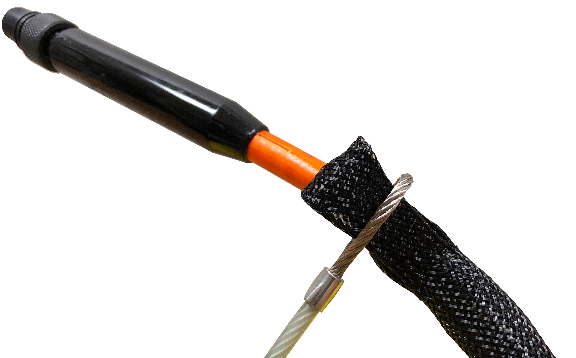
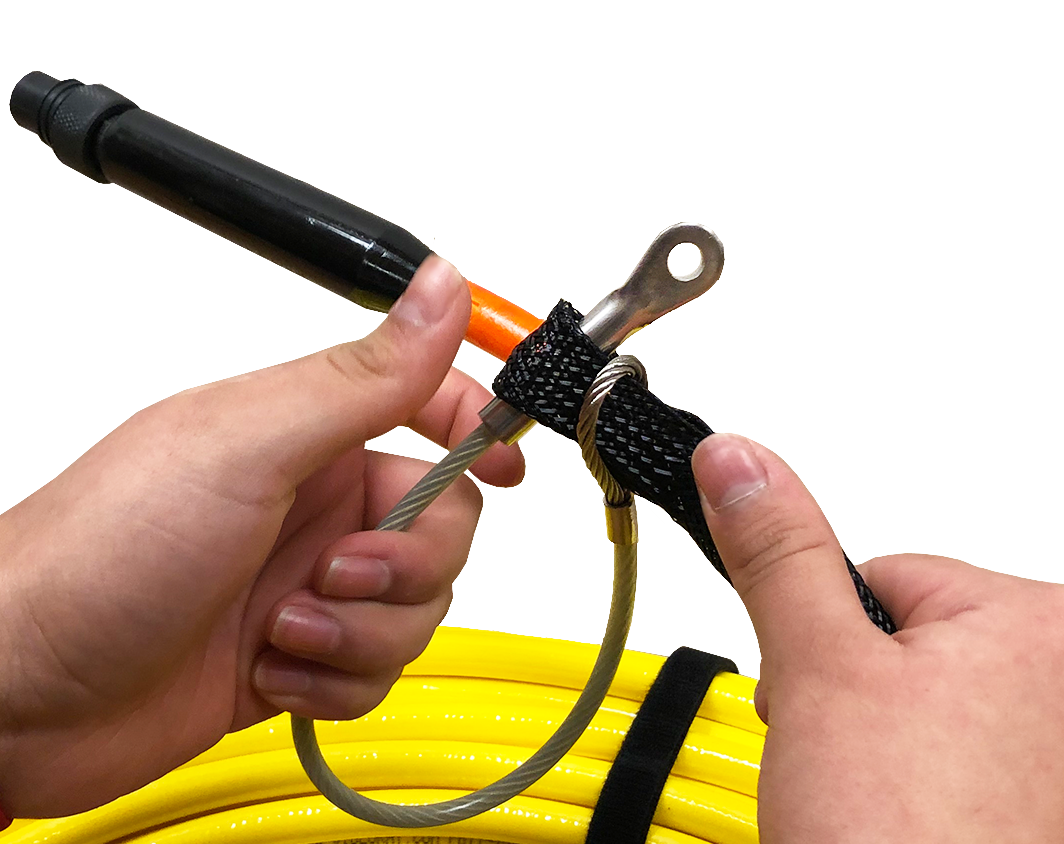
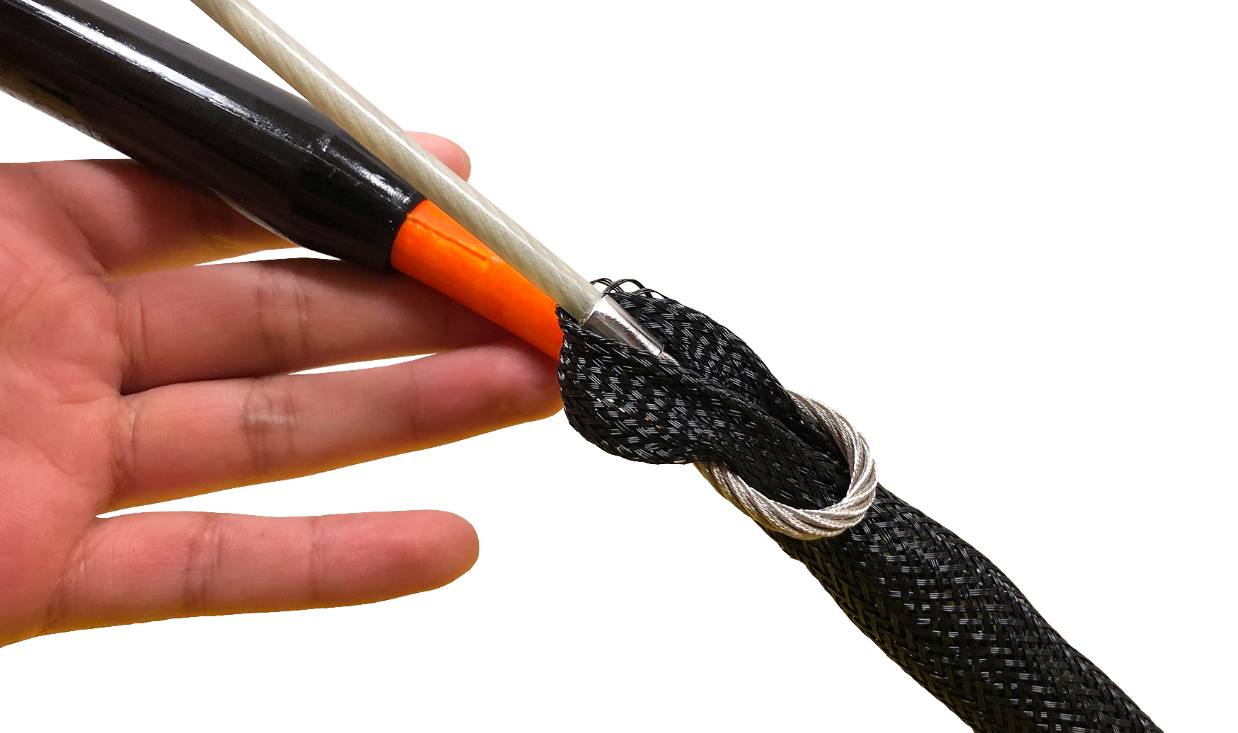
Tether Strain ReliefThe Defender strain relief is used to secure the ROV to the tether to prevent separation and loss of the vehicle if the tether connection becomes separated. The strain relief also minimized the load on the tether connector. There are two different strain relief systems. One is for use between the ROV and tether and the second is for use when connecting two tethers together. There is not a strain relief system for the topside connection. Instructions for using these strain relief systems is found on the following pages. |
ROV to Tether Strain ReliefUse the following procedures to install and secure the vehicle to the tether to prevent loss of the vehicle due to a connection failure. The strain relief cable may already be attached to the tether. If so, you can skip steps 1 to 3.
|
Tether to Tether Strain ReliefWhen connecting multiple tethers for an operation, each connection should be secured with a tether to tether strain relief to prevent separation of the connection. Use the following procedures to install and secure the strain relief cord for tether to tether connections. The ROV strain relief cable may already be attached to the tether. If so, it should be removed.
|
|
|
MSS Defender Operator's Manual, 1.00.00 |
Connections Summary
The following connections are required:
|
|
|
MSS Defender Operator's Manual, 1.00.00 |
AccessoriesNumerous accessories can be used with the MSS to extend its capabilities and range of performance. These accessories allow the MSS to support a wider variety of mission profiles. This section provides an overview of what accessory equipment is available. For up-to-date information, including new accessories and updates, visit http://www.videoray.com. For information about installing and using accessories, including operational recommendations, please see the guides provided with each accessory. Accessory Types
Accessory Categories
Accessory Sources
Accessory UseMultiple accessories can be connected in parallel by the use of a stackable connector. The manipulator and cutter do not use a stackable connector, but can be used with other accessories by plugging in their connector as the last one in sequence.
|
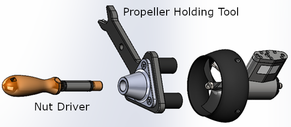
Included AccessoriesSeveral topside accessories are included with all Mission Specialist system configurations. Sun ShadeThe sun shade can be attached directly to the control panel lid and provides shade for the computer and monitor to make it easier to see the displays when working in bright light. See the label on the sun shade for installation instructions. Tool KitA basic tool kit is provided in order to perform routine maintenance and field repairs. The tool kit also contains some spare parts including ballast weights, propellers and other items. Additional Sensors and ToolingThis configuration includes the following sensors and tooling: |
Optional AccessoriesThe following pages provide information about the various accessories that are supported on the VideoRay Defender. Your configuration may or may not include all of these accessories. |
Rotating Manipulator |
GPSGPS (Global Positioning System) is used to locate the latitude and longitude of the ROV and the deployment location (vessel or dock). Topside GPS is used to identify the location of the the vessel or area where the pilot is working. VideoRay ROV GPS is located on the vehicle to determine the position of the ROV while on the surface of the water. |
Mission Support AccessoriesIn addition to the equipment that is included with each MSS configuration and the commercially available accessories, VideoRay recommends users procure a variety of mission support items. The list of recommended items will vary depending on the typical mission requirements, although it will be obvious that some of these items have general applicability to all mission profiles. These brief lists are intended to provide a sample and stimulate thinking about what you might want to add to your "operations kit:" General Logistical Support
Tactical Operations Support
|
|
|
MSS Defender Operator's Manual, 1.00.00 |
Software GuideMission Specialist software consists of three main components:
The topside Operator interface software is available in several versions:
|
|
|
MSS Defender Operator's Manual, 1.00.00 |
Greensea User Manuals for the DefenderGreensea control software comes in three versions:
|
|
|
MSS Defender Operator's Manual, 1.00.00 |
VideoRay Interface OverviewThere are four applications that are required to operate the VideoRay vehicle control software. These are stored in the ~/Flighthack folder.
Each application may be started in any sequence, but following a consistent sequence such as above is recommended. |
|
|
MSS Defender Operator's Manual, 1.00.00 |
Software ManagementThis section provides information about the software environment and managing the software. |
Folder StructureHome/ - User Root Folder charts/ - Recommended location for charts firmware/ - Module Firmware flighthack/ - Mission Specialist Utilities gss_config/ - Configuration Files gss_logs/ - Recordings gss_mission/ - Mission Definition Files |
Software UpdatesSoftware updates can be downloaded from https://videoray.exavault.com/ Username: quarterdeck
The new version should be installed and ready to run. Contact VideoRay support if you need assistance. |
|
|
MSS Defender Operator's Manual, 1.00.00 |
Module ConfigurationThe modular concept requires that modules be configured prior to installation or replacement in a specific vehicle arrangement.
Conceptual OverviewThrusters and other modules can be thought of as employees, and the vehicle as the jobsite. Each employee (Module) has a unique name (Serial Number stamped or printed on the module and coded in the firmware). When the employee goes to work at the jobsite (is installed on the vehicle), it is assigned an employee number (Node ID) by the person doing the configuration. The jobsite supervisor (control software) communicates with the employees using their employee number, so the employee number for each module on a jobsite must be unique. Work instructions are announced to all employees at the same time, so each employee must listen for their specific instructions and ignore the instructions for other employees. When there are multiple employees of the same type on a jobsite, these employees may be assigned specific work tasks (Application ID or Motor ID). The employee will only listen for instructions related to their work task. For example a starboard thruster will only respond to horizontal control inputs, while a vertical thruster will only respond to vertical control inputs. This approach allows vehicles to be configured with great flexibility. Examples include:
General Requirements
The following sections provide information about module replacement. |
Configuration CommandsThe following configuration commands are available for updating firmware and configuring M5 modules for MSS vehicle systems:
More information about using these commands can be found in the following section of this guide. |
Command: vr_refreshThe vr_refresh command is used to update the firmware on a module. Usevr_refresh [OPTIONS] [SINGLE_HEX_FILE_NAME]
|
Updating FirmwareFirmware can be found locally in the Home/firmware/ folder. The most up-to-date firmware is available from VideoRay's FTP server. You can download the firmware to the local folder by connecting to the Internet and using the following command:
Example firmware update commands for different modules are shown below. In each case, X.Y.Z should be replaced by the actual version number. Each vr_refresh command should be entered on one line. Ignore any line breaks that may appear in the vr_refresh commands displayed below. Power Module
Communications Module
AHRS Module
Thruster Module (Use the correct Node ID)
Camera Module
LED Module (Use the correct Node ID)
Firmware Block Sizes
|
Command: vr_enumThe vr_enum command is used to enumerate (list) the modules that are connected to the vehicle. Usevr_enum [OPTIONS] [min explcit id] [max explicit id]
Examples
For Power, Communications, Thrusters and LEDs
For the AHRS and camera modules, you need to include the virtual port. AHRS Module
Camera Module
|
Command: vr_setidThe vr_setid command is used to set the Node_ID and Group_ID of a module. Usevr_setid [OPTIONS] SN Node_ID Group_ID
Examples
For the examples below, replace "S.N" with the actual serial number. The serial number is case sensitive. Power Module
Communications Module
AHRS Module
Thruster Module (Use the correct Serial Number and Node ID)
Camera Module
LED Module (Use the correct Serial Number and Node ID)
|
Command: vr_debug_putty.pyThe vr_debug_putty.py command is used to configure or test a module. Use./vr_debug_putty.py [OPTIONS] [N [N...]]
Power Module
Communications Module
AHRS Module
Thruster Module (Use the correct Node ID)
Camera Module
LED Module (Use the correct Node ID)
|
Command: vr_create_virtport_all.shThe vr_create_virtport_all.sh command is used to create virtual ports that allow the Ethernet protocol to be used to communication with modules connected to the communications module. Virtual PortsMSS communications are supported using Ethernet and RS-485 protocols. Modules may use one protocol or the other, or both. The configuration commands described on the previous page, including vr_enum, vr_setid, vr_refresh and vr_debug_putty.py use only the RS-485 protocol. For modules that only support Ethernet, a virtual port must be set up to bridge the RS-485 to Ethernet for the Communications Module port to which the device is attached. The vr_create_virtport_all.sh can be used to create the required virtual ports. Use./vr_create_virtport_all.sh & There are no arguments for this command.
Example Using Virtual Ports to Communicate with a CameraThis example assumes that a Camera Module with serial number CAMADP000123 is plugged into port 2 of the Communications Module.
|
|
|
MSS Defender Operator's Manual, 1.00.00 |
Operations GuideThis Operations Guide is provided to go beyond the Equipment and ROV control software guides to describe not just how the MSS works, but how to work with the MSS. There are numerous topics and tips that are outside of the scope of conventional system documentation that focuses only on the hardware and software. You will find recommendations and best practices, but you are also encouraged to use your best judgment and apply all of the information in this documentation and your experiences to your specific applications. In addition to this guide, there are other sources of information about ROV operations that you might consider. These include training, support and user forums. There are links to these resources at the bottom of each page. The Community Link at the bottom of the page provides access to http://www.rovinfo.com, which is a great resource to meet other VideoRay and ROV operators and exchange information and tips with them.
|
|
|
MSS Defender Operator's Manual, 1.00.00 |
Acceptable UseThe ROV system was designed to be operated in accordance with the instructions in this manual. Make sure to use a power supply that meets the stated requirements and is in safe operating condition. Do not exceed the depth rating. Uses of the ROV system other than for its intended design purposes and environments should not be attempted. If you have any questions about use of the ROV in specific situation or conditions, contact VideoRay. |
System Voltage AdvisoryAC InputInput voltage is universal at 100-240 VAC; 50, 60 Hz. The power requirement for the Mission Specialist operating at full power settings is 3,000 Watts. A 2,000 Watt source (i.e. generator) can be used if the system will not be used at full power settings. ROV DC PowerHistorically, the tether voltage to power the ROV has been increasing. Economy models (including the Scout, Explorer and Voyager), Pro 3 variants and the Pro 4 Ultra use 48 V DC for vehicle power. The Pro 4 uses 74 V DC. Mission Specialist systems uses 400 V DC with plans to use higher voltages in the future. Systems with voltages higher than 48 V DC include a LIM (Line Insulation Monitor) protection module in the ROV DC circuit.
VideoRay Negative, Neutral and PPT tethers are rated to 600 V DC and are safe to use on any system through the Mission Specialist 400 V DC.
The new version of the extended TDS is available that includes a 600 V rated slip ring. If you have any questions about system voltage and compatibility, contact VideoRay Support. |
Environmental and Chemical CompatibilityThe VideoRay MSS is designed and approved for use in fresh or naturally occurring salt water and non-hazardous fresh air environments. While VideoRay recognizes that some customers may desire to use the vehicle in other solutions or environments, such use is entirely at the discretion and liability of the customer and doing so may void the product warranty. The following additional solutions have been researched by VideoRay and use in these solutions is deemed to fall within the acceptable use guidelines and will not affect the warranty.
TemperatureThe maximum recommended temperature for sustained use is 50 C. Non Approved Solutions and Environments
VIDEORAY EXPLICITLY DOES NOT CONDONE THE USE OF ITS PRODUCTS IN ANY SOLUTIONS OR ENVIRONMENTS OTHER THAN THOSE EXPLICITLY LISTED ABOVE, AND ASSUMES NO LIABILITY FOR USE IN OTHER SOLUTIONS OR ENVIRONMENTS. Risks of using VideoRay Systems in Non Approved Solutions or Environments may include, but are not limited to:
USE OF VIDEORAY PRODUCTS IN OTHER SOLUTIONS OR ENVIRONMENTS IS ENTIRELY AT THE DISCRETION OF THE CUSTOMER / OPERATOR AND THE CUSTOMER / OPERATOR ASSUMES ALL LIABILITIES FOR SUCH USE. |
ROV Materials ListThe following is a list of materials used in the vehicle: Open this document in new Window Users may check this list against chemical compatibility charts available from several sources. This information is provided for convenience. Providing this information does not explicitly or implicitly extend the warranty to cover the use of VideoRay products in solutions that are not specifically listed in the Environmental Compatibility section. VideoRay is not responsible for errors or omissions in any of the presented information.VideoRay can provide engineering services for a fee to determine chemical compatibility. Contact VideoRay for more information. |
|
|
MSS Defender Operator's Manual, 1.00.00 |
Project ManagementWhile the differences between conducting a recreational dive, an inspection of an offshore well riser, and a drowning victim recovery are quite dramatic, each of these dive missions usually consist of the following phases:
Of course, how critical a successful outcome is deemed and how much lead time and how many resources are available will dictate how much effort can or will be afforded to each phase. The essential knowledge and skills required for a consistent ability to "get the job done" go well beyond just being able to set up and pilot an ROV. In this section, the following topics will be discussed to help broaden your understanding of the scope of practical ROV applications. |
Mission PlanningOnce the basic objectives for an ROV mission have been established, there are several additional, and critical, requirements that need to be identified before rushing off to the dive site. Each of these additional requirements can be defined by developing a list of questions and thinking through the answers. Some of the answers may lead to more questions. With the information gathered by answering the questions, appropriate decisions can be made and your plan developed. Below is a representative list of requirements and corresponding questions. This list is not comprehensive, and is only intended to serve as a guide for you to develop your own list of appropriate requirements and questions.
Additional Notes
|
General LogisticsIn addition to the ROV system and its accessories, you will typically need to provide other equipment to support your mission. The first items on your list should be those required for safety of the crew, such as personal flotation devices and a first aid kit. Depending upon your specific requirements that should have been identified in the planning phase, recommended equipment might also include:
VideoRay Power RequirementsThe VideoRay MSS operates on 100-240 Volts AC, 50,60 Hz. This can be provided from the land-based grid, a generator, or a battery with an inverter. Minimum generator or inverter requirements are 3,000 Watts. TransportationLand or water transportation will likely be required and you will need to ensure that you have enough space for your crew and equipment. You may also want to bring maps or charts of the operating area, and you should try to ascertain access points and plan your route accordingly. Carts to transport equipment while at the site may be helpful if the terrain is accommodating. Site-specific RequirementsOften, river or shoreline sites have steep banks. For these locations, you might want to bring rappelling equipment or at a minimum some ropes to assist in climbing or transporting equipment up and down. Sea sickness remedies for vessel operations can make the difference between a successful mission and an aborted attempt. Unequal Grounds
|
On-site OperationsOn-site operations can be hectic and demanding. The following information can help maintain order and productivity. Site Selection and System Set UpThe following recommendations should be considered when selecting a site and setting up the equipment:
The ROV Team, Their Roles and ResponsibilitiesWhile one person can operate a VideoRay, having multiple people participate can be valuable or may even be required in some situations. The following roles and responsibilities are suggested to assist in developing an efficient and effective ROV team.
Additional Notes
|
Video RecordingVideos are .MP4 format, named by date and time and are stored in the Home/gss_logs folder. |
Project CompletionOn-site, the system should be cleaned as best as possible and stowed for transport. Be careful when closing lids to avoid pinching any cables or damaging the video display components of the computer or the control panel. Upon return to the home base, other tasks that should be considered before stowing the equipment include:
Project DeliverablesOften, the completion of a project means delivering a product, such as images or videos of an inspection, or retrieval of an item. These can be delivered as isolated products or as part of a formal report. See the Images and Videos section of the Operations Guide for more information about still image and video post-processing and production. |
Image and Video Editing and ProductionYou can record snapshots and video. You can edit and produce video files or DVDs. The following sections provide more information on each of these steps. The best quality output requires good input. Adjust the lights and focus to give the best starting image quality. More light does not always provide a better picture - back scatter from particles can obscure your intended objective. Light position can also make a big difference. Auxiliary lighting from the side can produce an image that looks like it was taken in air. |
Video Snapshot ImagesSnapshot Images are .JPG format, named by date and time and are stored in the Home/gss_logs folder. |
Data ManagementImages and videos captured during a mission are store in the Home/gss_logs,. These files should be moved to a project folder after each mission so that the imagery folder does not get overpopulated with mix of files from various projects. When viewing files, it can be hard to distinguish one underwater location from another. Preferably, these files should also be backed up to separate media. |
|
|
MSS Defender Operator's Manual, 1.00.00 |
Emergency Situations
During the course of operations, it is possible that an emergency situation may arise. The following rules of thumb apply to all emergency situations:
|
Emergency Response to a Flooded ModuleIf you suspect that a module is experiencing a leak during operations, there are four critical steps to remember:
Additional details are provided below, but it is important that you cut the power as soon as a leak is suspected and clean and dry the system as soon as possible. You should not attempt to "test" the equipment until you are sure it is completely dry. Turning the power on while the components are wet will likely cause more damage. The following detailed procedures will not guarantee recovery from a flood incident, but they will provide the best chances of salvaging as much as possible
|
Emergency Response to a Snagged Tether/ROVIf the tether or ROV appears to be tangled or stuck, remember: Do NOT Panic! Do NOT Pull the Tether! The first step is to assess the situation. Above all, you do not want to make the situation worse by trying to maneuver without knowing whether doing so will help or hurt. If you can maneuver the ROV, try to turn around until you find the tether and follow it back to the point of the snag. You may need to turn left and right and with the camera looking up and down in order to find the tether. If you are sure there are no knots in the tether, or it is not likely to get snagged tighter, you can try to pull the tether from the surface or by using the ROV to pull it away from the snag. Tips and Possible OptionsIf you have a manipulator on the ROV, you may be able use it to assist with the untangling process. Even if you don't have a manipulator, you may be able to use a part of the ROV such as the skid to assist with manipulating the tether. If you have a second ROV system available, you may be able use it to fully assess the situation and develop a plan or even assist with recovery. If you can pilot the ROV to the surface, you can disconnect it and try to retrieve the loose tether. Make sure to turn off the power before disconnecting the ROV. Thoughts on Being PreparedUntangling a tangled or stuck tether is an important part of all ROV Pilot's training. If you have not been trained in these and other emergency procedures, you should consider participating in such training. Good pilots will also regularly practice untangling the tether and ROV along with other piloting exercises. |
Emergency Response to a Cut TetherIf the tether is suspected of being nicked or cut, follow these steps:
Tether Field RepairHot glue or Silicone / RTV glue can be used to repair a tether in the field. These items should be considered for inclusion in a field tool kit. Field repairs should be repaired using more permanent techniques at the first opportunity. |
Emergency Response to a Loss of FunctionIf control of the ROV is lost, follow these steps:
Loss of function often results from a hardware problem. Assuming the ROV can be recovered, remove the tether and connect the ROV directly to the control panel. This will isolate the problem to either the tether or some other component. |
Emergency Response to Loss of ControlIf you suspect that the ROV is not responding to control inputs as it should, there may be several causes:
|
|
|
MSS Defender Operator's Manual, 1.00.00 |
Universal PracticesSeveral practices are common to almost all ROV operations. This section provides some guidelines for the practices. |
Deployment PlatformsVideoRay ROVs can be deployed from land, vessels, remotely or even some very unique situations. Power can be provided by a shore based system, a generator or a battery with an inverter. Height above Water SurfaceVideoRays can be deployed from a significant height above the water surface by lowering the vehicle by its tether. LandFor land-based deployments using shore power the biggest issue is usually how close can you get to the water. When operating in tanks, beware of active inlets or discharges and avoid using the ROV or tether near these areas. Many tanks also have cathodic protection systems, which can become a snare and entrapment hazard to the ROV. VesselsWhen operative from vessels, it is important to be aware of potential risks to personnel or the equipment. Whenever possible, conduct ROV operations when the vessel is at anchor or adrift without the propulsion system engaged. When the vessel's propulsion system must be engaged during ROV deployment, tether management is critical to ensure the tether or the ROV do not come in contact with the vessel's propulsion systems. Water intakes and discharges can also be hazardous to the ROV and should be locked out or the ROV and tether kept a safe distance. Remote OperationsVideoRays can be operated remotely using Internet technologies. See the section on Using Network Remote for more information. OtherOther unique deployment platforms include:
|
Tether ManagementTether management can have a significant affect on the ability to pilot the ROV and achieve the objectives of the mission. Tether Management includes selecting the appropriate type of tether and managing the deployment and retrieval of it during operations.Choosing the right tether and managing it can have a very significant impact on the outcome of an ROV dive. Tether is available in neutral or negative buoyancy. Negative tether sinks but has larger conductors, which means longer lengths can be used without affecting the power available at the ROV. Neutral tether is neutral in fresh water (slightly buoyant in salt water), but has thinner conductors. Neutral tether is available in standard diameter and performance diameter (also called PPT), which is thinner. Thinner tether has less drag, but also has smaller conductors and less power transmission capacity. Selecting the right tether is a balancing act between performance and handling characteristics. General Tether Use Recommendations
Tether StorageMake sure the connectors are clean before mating, and clean the connectors after each use by soaking in fresh water. Do not let the tether connectors drag on the ground. Tether should be stored on a TDS or coiled using an over/under or figure eight technique. Coiling the tether in one direction will result in twists that are hard to remove. |
Special SituationsCertain environmental situations, such as temperature extremes, water contaminants and others may call for special handling and procedures. The following sections provide some suggestions for operating in these conditions. |
Cold Weather OperationsThe system may act sluggish in cold weather conditions. If you must operate in conditions with ambient temperatures below 32 F (0 C) Follow these steps to minimize the effects of cold on the system.
|
Hot Weather OperationsThe control panel can overheat in hot weather. If you must operate in conditions with ambient temperatures above 90 F (32 C) Follow these steps to minimize the effects of heat on the system.
|
Equipment Disinfection for Use in Potable WaterVideoRays are used by many companies for inspections in potable water systems. Always check with regional and local authorities for specific regulations and compliance requirements regarding the use of ROVs in potable water systems.
At the time this document was compiled, the MSS thrusters use an oil and dye that have not been rated for use in potable water systems. The MSDS and other product information for the oil is available: Oil MSDS Oil Product Data Sheet. The MSDS for the dye is also available: Dye MSDS. Please check with VideoRay regarding the current specifications for thruster oil and use in potable water systems. The following procedure to disinfect the ROV prior to entering a potable water tank is recommended by John Conrady of Conrady Consultant Services and is used with permission.
|
Use in Contaminated Water or Other Liquids
The information provided here is solely to alert you to the possibility of these dangers and is not a comprehensive treatment of this topic. You should seek professional advice from experts for the conditions in which you plan to operate if you must operate in anything other than naturally fresh or salt water.
Use of VideoRay equipment in contaminated water or other liquids is not recommended and damage to the equipment from operating in such conditions is not covered under warranty. USE PPE (Personal Protective Equipment)If you think there is the possibility of contaminants in the water or liquid in which you are operating, Personal Protective Equipment appropriate for such contaminants is strongly advised. Bio-HazardsBio-hazards include both working in potable water and ensuring bio-hazards are not introduced into the water system by the ROV (see the section on Use in Potable Water), and working in bio-hazard contaminated water such as in or around water treatment plants or effluents. Equipment Decontamination after Use in Bio-hazard Contaminated WaterStandard post-dive procedures call for soaking the ROV and tether in fresh water for at least 30 minutes. In situations where the equipment is used in water suspected to contain contaminants, you can review US EPA guidelines documents regarding contaminated water and divers and dive equipment.
Chemical CompatibilityUse of VideoRay equipment in liquids other than water should be checked against standard chemical compatibility charts, available from a variety of sources such as Cole-Parmer. For situations where poor chemical compatibility ratings exist, it may be necessary to avoid use altogether, or replace parts after use. For more information about chemical compatibility, contact VideoRay. Additionally, post dive procedures such as those in the US EPA guidelines documents regarding contaminated water and divers and dive equipment, or other more aggressive procedures may be employed to clean the equipment after use. You should also check the chemical make up of any cleaning agent to ensure that it does not react adversely with the equipment.
Volatile Environments
|
|
|
MSS Defender Operator's Manual, 1.00.00 |
PilotingPiloting a VideoRay ROV requires a combination of understanding the system's operating principles, features and capabilities, situational awareness (which is much more challenging when you cannot see the vehicle), personal skills and experience. The VideoRay MSS Systems have several pilot assist tools that provide auto control of the vehicles functions and other sensors that help with situational awareness. Several optional accessories can provide even further situational awareness, such as sonars and position tracking systems. Autonomous operation is also possible through advanced navigation control software. The following sections provide information about built in pilot-assist tools and piloting tactics for specific situations. |
Piloting ToolsVideoRay MSS control software provides several tools to assist the operator when piloting the ROV. These include:
Auto Flight and Course Following Checklist
|
Auto ModesAuto Modes on the Mission Specialist operate differently than on the Pro 4. On the Pro 4, auto modes are engaged when the inputs (heading or depth) are in their neutral position. When the operator applies input, auto mode temporarily disengages and reengages when the input is returned to neutral. When in auto flight mode on the Mission Specialist, joystick inputs control set points. When the input is neutral, the set point remains constant. Inputs are used to control the set point. Auto modes are much more fly-by-wire. If you are familiar with auto modes of the Pro 4, caution should be observed to monitor the set point. |
Auto HeadingAuto Heading can be used to maintain an existing Heading, or turn the ROV to a specified Heading. Auto Heading is designed to be as seamless as possible so that you can pilot without having to constantly engage and disengage it when alternating between holding a course and changing directions. How Auto Heading WorksWhen Auto Heading is engaged, the ROV will automatically respond to changes in heading (measured by the compass) by applying horizontal thrust to maintain the current heading. Using Auto Heading to Hold a HeadingTo engage Auto Heading, click on the Auto Heading button. This will engage Auto Heading at the current heading. You will also notice a heading value in square brackets in the text overlay and a green heading indictor in the compass. These indicate the target heading. To turn to a new heading, either turn the ROV using the joystick until the target indicator reaches the desired heading, or type in the heading next to the Auto Heading button and click the Apply button. Additional Notes
|
Auto DepthAuto Depth can be used to maintain an existing depth, or surface or dive to a specified depth. Auto Depth is designed to be as seamless as possible so that you can pilot without having to constantly engage and disengage it when alternating between hovering and changing depths. How Auto Depth WorksWhen Auto Depth is engaged, the ROV will automatically respond to changes in depth (measured by the pressure sensor) by applying vertical thrust to maintain the current depth (pressure).
Using Auto Depth to HoverTo engage Auto Depth, click on the Auto Depth button. This will engage Auto Depth at the current depth. You will also notice a depth value in square brackets in the text overlay and a green depth indictor in the depth display. These indicate the target depth. To move to a new depth, rotate the depth control knob using the joystick until the target indicator reaches the desired depth, or type in the desired depth next to the Auto Depth button and click the Apply button. Additional Notes
|
Station Keeping
Station Keeping will maintain the current location of the vehicle. If auto heading and/or auto pitch is on, the orientation will be maintained as well. Auto modes will only maintain a specific parameter and if there are currents or the tether is pulled, the location may change. |
Course Following
While auto modes maintain specific parameters, course following allows operators to direct the motion of the vehicle by means other than the joystick. This includes moving the vehicle in incremental amounts, going to specific locations, or setting up a course to follow. |
Incremental MotionIncremental motion controls can be used to move the vehicle a specified amount through various degrees of freedom, including forward or back, laterally left or right, changing heading or up and down. The motions can be controlled independently and the increments can be set to desired values. |
Go to...Go to modes include, go to a position (selected by clicking on the screen), go to a marker (whose location set by mouse or key-in), or go to waypoints (whose location is set by mouse or key-in).
|
Waypoint RouteWaypoint Routes can be defined and the vehicle will follow the course defined by the waypoints. Waypoints can be selected by mouse or entered by coordinates. Course controls include setting a tolerance for establishing whether a waypoint is achieved or not, head towards waypoint or crab, speed between waypoints and whether depth should be considered a criteria for achieving a waypoint or not (the system will try to achieve the waypoint depth, but this feature allows the course to continue if the depth is not achieved). There are also override controls that can be used during the waypoint route following to change the order or speed of the course. |
Power ManagementPower utilization in Mission Specialist systems is demand based. If vertical thrusters demand more power for lifting operations, the system responds up to its capacity based on the topside power supply output from the Operator Control Console and the tether's capacity to deliver that power to the ROV. This design feature allows VideoRay to maximize the performance of the vehicle for specific tasks. This also means that the system can, at times, demand more power than can be delivered, which could result in a system brown out. The system is protected, so a brown out is not harmful to the components, but it can cause the system to reset. Power utilization depends on several factors, including: rapid manual or autonomous control inputs, the intensity of the lights, the attached accessories power demand, the amount and type of tether being used, water currents, etc. There are two design options when dealing with this situation. The first is to reduce the allowed power consumption of all of the components combined to never exceed the capacity of the topside and longest tether possible. While this would prevent brown outs completely, the system could never take advantage of the fact that when lifting, horizontal thrust may not be required, or when working with short tethers, more power can be delivered to the ROV than when operating with longer tethers. The second is to allow each component to demand as much power as it can up to its maximum design capability. This can result in a total power demand that exceeds what is available, but maximizes selected performance when required. VideoRay has chosen to implement this second option. Power Management ImplementationVideoRay is working to improve the power management software of the system to automatically adjust the power utilization and prevent brown outs.
In the interim, the Greensea control software includes a manual power setting. This setting can be found in the Power tab under the video display. The default value is 65% as seen in the upper right of the image below. You can change the power setting to increase the power utilization or reduce the incidence of brown out by sliding the slider. To increase the power utilization, move the slider to the right towards 100. To decrease the power utilization, move the slider to the left towards 0.00.
|
Piloting TacticsPiloting a VideoRay is generally easy in clear, calm water and can be learned quickly. Real world operations are generally more challenging and demanding. Pilots should be comfortable in clear calm water before attempting more challenging conditions. Unless you work in a controlled environment, such as tanks, you are likely to encounter low visibility, current, deep conditions, or even all three. Each of these takes special techniques or accessories.
|
Piloting in Low VisibilityWhen piloting in low visibility, there are several techniques that can be used to help you navigate to your objective or find and observe your target.
Depending on the objectives, depth and distance, low visibility may require an accessory like sonar and/or a position tracking system. |
Piloting in Swift CurrentWorking in current presents challenges that you may not be able to overcome if the current is too strong, but there are several strategies that you can apply depending upon the situation. Current can be consistent throughout depth, or there may be wind driven current on the surface, and tidal or other currents below. This will of course complicate the situation, but there are techniques to try before giving up.
|
Piloting in Deep WaterWorking in deep water presents its own set of challenges.
|
Piloting in Confined SpacesWhen piloting in confined spaces, the gravest concerns are getting stuck or getting the tether snagged on an obstruction. The best techniques are:
If the ROV or tether does get stuck, assess the situation as best as possible in order to avoid making the situation worse. See the section on Emergency Response to a Snagged Tether/ROV for additional tips. |
|
|
MSS Defender Operator's Manual, 1.00.00 |
Remote Operations and StreamingMission Specialist systems can be controlled remotely over the Internet or set up to stream video to remote destinations.Requirements
Configuration Overview
The local or remote control or viewing computer is connected to the Operator Control Console locally over a LAN or remotely over a WAN using TeamViewer software. When set up, this computer can control the ROV and/or be used for viewing only. If additional remote locations require viewing, these can be connected to the local or remote control or viewing computer using a virtual meeting application like Microsoft Teams, Zoom, Google Meet and other similar applications.
Configuration Set Up InformationTo connect the local or remote control or viewing computer to the Operator Control Console, follow these steps:
To add optional remote viewing locations follow these additional steps:
Internet Configuration Issues
|
|
|
MSS Defender Operator's Manual, 1.00.00 |
Maintenance GuideThis section will describe the maintenance requirements and procedures for periodic or common maintenance requirements. It will not be detailed enough to be considered a component level repair manual, but will address component replacement of modular components. |
|
|
MSS Defender Operator's Manual, 1.00.00 |
User Maintenance PolicyUser's are ultimately responsible for the safe operation and longevity of their VideoRay equipment by minimally following best practices outlined in the Operator's / Maintenance Manual, recognized industry standards and using common sense.
VideoRay also understands that logistics and other issues may make it difficult and costly to return the equipment to a Factory Authorized Service Center for completion of some of the simpler procedures. The following procedures are considered acceptable for the owners and lessees to complete without impact on the warranty. Note that cleaning components is a required condition for continued warranty protection and that failure to exercise reasonable care during these procedures may result in warranty claims being denied.
Instructions for performing these procedures are included in the Operator's / Maintenance Manual. Users who do not feel comfortable completing these procedures are invited to contact VideoRay for assistance.
|
Basic Equipment CareDo not abuse the VideoRay and be careful not to damage the system's components through normal use. For example, avoid letting the tether connectors come in contact with the ground where rough surfaces or dirt can damage the contacts. CleaningVideoRay systems should always be cleaned after use. When used in salt water or contaminated environments, make sure to thoroughly rinse and then soak all wet components. It is especially important that you rinse the pressure sensor and allow it to drain. You must remove the float block to do this.
Storage and TransportAlways pack the system securely to make sure it is not damaged in transport. |
Periodic MaintenanceThe following tables provide information for periodic inspection and maintenance. All users should follow these guidelines, however, some repair / replacement procedures require advanced training.
|
|
|
MSS Defender Operator's Manual, 1.00.00 |
Maintenance Best Practices
The best maintenance programs begin before trouble occurs, and preventative maintenance should be your first step on the road to reliable system performance. InspectionsInspections should be carried out before and after every dive as part of the pre- and post-dive procedures. Be observant for signs of loose parts, wear or impending failure - catch small problems before they become big problems. A
Trained OperatorsDo not subject equipment to accidental or inadvertent abuse by someone who is not trained in its proper use.
Trained TechniciansMaintenance should be completed by trained and certified technicians, and using factory authorized parts. VideoRay recommends that you create and maintain a system logbook. The logbook entries can include details of missions (date, location, conditions, dive time, etc.) and maintenance performed (date, procedure, parts replaced, etc.). The logbook may help identify possible causes of problems and systemic issues that should be reported to VideoRay for further investigation. ServiceFollow recommended periodic maintenance schedules, documented procedures and use the proper tools. Work in a clean environment. For any service or repair procedure beyond the scope of the simpler procedures defined in the User Maintenance Policy, contact VideoRay for assistance. |
Well Equipped ShopA well equipped shop is organized, clean, and well lit. Ideally all work can be conducted in such an environment, however there may be times when maintenance or repairs must be completed in the field. For those occasions, Maintenance Tools RequiredVideoRay is designed with ease of maintenance in mind, and only a few tools are required to service the system. In fact, many maintenance procedures, such as changing light modules can be done without tools. VideoRay also includes a small tool and spares kit with each system delivered that contains most of the required tools. The following list of tools is recommended:
* - These items are not included in the standard tool kit that comes with MSS systems. Additionally, small trays to hold parts and fasteners are recommended. Field Tool KitIdeally all work can be conducted in a workshop environment, however there may be times when maintenance or repairs must be completed in the field. For those occasions, it is recommended that you carry a well stocked tool kit, and a clean mat that can be used as a clean workspace for maintenance. |
Special Handling
|
Connector Care and HandlingConnectors should be handled with care and inspected and cleaned regularly. Always follow any specific instructions provided by the manufacturer for connector care. The following general guidelines are provided to help extend the life of the connectors.
Specific Instructions from the Manufacturer for IE55 Connectors (used on the BluePrint Sonar, Manipulators, USBL)
|
Tether Care and HandlingTethers should be handled with care and inspected regularly. The following general guidelines are provided to help extend the life of the tethers. Tether connectors and connections
Tether Operations
|
O-Ring Care and HandlingO-Ring Rule of Thumb - If in doubt, throw it out! Generally, when compared to the equipment they are protecting, O-rings are very inexpensive. Should an incorrectly sized or damaged O-ring be installed, the result can be catastrophic. If there is any doubt as to the suitability or condition of an O-ring it should be replaced.O-rings and other components with sealing surfaces should never be handled with dirty or gritty hands. A small amount of dirt trapped next to an O-ring will cause leakage, which could result in serious damage to the ROV's internal components. The most common situation is a single strand of hair or lint, so care should be taken to ensure a clean work area. Should an O-ring or sealing surface become dirty, wash it with mild soap and water, and then rinse it with clean water. Avoid scratching the surfaces of the O-ring grooves and landings. Do not use sharp objects such as a knife or screwdriver to pry apart sealed assemblies or remove O-rings. Serious damage to the O-ring or the seat may result. O-ring Lubrication - VideoRay recommends the use of pure silicone spray or the O-ring lube kit that comes in the standard tool kit. Other lubricants can lead to deterioration and failure of the O-rings and components. Do not use other lubricants! Other lubricants may cause deterioration or attract dirt and lead to leaks or premature failure. O-ring Inspection - O-rings wear out over time. Inspect all O-rings whenever a sealed assembly is apart. "Healthy" O-rings are soft, flexible and have not been pinched or nicked. Should an O-ring appear brittle, or have apparent cracks, nicks, or evidence of being pinched or permanently compressed, it should be replaced. Sealing surfaces should also be inspected while an assembly is apart. The surfaces should be examined to determine that they are free of dirt, nicks, scratches, or damage, which may result in seal failure once reassembled. O-ring Storage - O-rings should be stored in clean plastic bags to protect them from dust when not in use. Avoid prolonged storage in direct sunlight as this may result in deterioration of the O-ring material. Stored O-rings should be sorted with regard to type and size with that information noted on the storage bag. Use of an incorrect O-ring can result in an ineffective seal. |
Electronics Components Care and HandlingElectronic components (circuit boards) are susceptible to damage from ESD (Electro-Static Discharge). Numerous sources are available that provide background information and recommend procedures for handling these components. These procedures should be followed when directly handling VideoRay's electronic components. ESD is caused by the build up of static electricity. Steps to reduce the build up of static electricity or drain off any static build up are encouraged in order to prevent ESD damage. General Guidelines for handling electronic components include:
If you cannot work in a properly equipped ESD safe area, there are some general precautions you can follow in addition to the above.
|
Hull Materials Care and HandlingAluminum Hull ComponentsVideoRay's aluminum parts are protected by anodizing and/or ceramic coatings. The use of metal tools can scratch these coatings leading to corrosion. Be careful when working with with metal tools near hull parts. Use only wood or plastic tools when the tool must contact an aluminum hull component. Main Dome and Light DomeThe domes should be cleaned with mild soap and water. They are acrylic and small scratches can be buffed out.
Galvanic CorrosionGalvanic corrosion results from dissimilar metals being in contact when exposed to a conductive medium like salt water. Make sure all stainless steel fasteners are not in direct contact with aluminum hull parts. VideoRay uses nylon spacers for these contact points to keep the materials separated. Always make sure to use these spacers when reassembling parts after routine maintenance or a repair. |
|
|
MSS Defender Operator's Manual, 1.00.00 |
Configuration / Calibration |
Compass CalibrationFor the best navigation performance, the compass should be calibrated in the following situations:
Step-by-Step Procedures
|
|
|
MSS Defender Operator's Manual, 1.00.00 |
Diagnostics and RepairAre you having a bad day with your Mission Specialist system? You have come to the right place. Solving problems requires either a methodical diagnostics approach, or lots of luck. If you don't like to gamble, the following may help you overcome challenges that inevitably present themselves from time to time. Before providing the specific details of diagnosing and repairing the MSS?, some basic troubleshooting guidelines are in order. Following these practices should make your efforts much more efficient and successful.
The MSS is a collection of relatively simple components, but when something goes wrong, it's easy to get overwhelmed. The following steps should be your first response to a general system malfunction, especially if the power and communications warning indicators in the ROV Health instrument are lit.
If the problem is more isolated to a specific function, or these steps fail to resolve a general problem, it's time for a closer look at the symptoms and subsystems. |
|
|
MSS Defender Operator's Manual, 1.00.00 |
Propeller MaintenancePropellers are considered wear items and should be inspected before every dive during the Pre-Dive Setup procedures.
Propeller Replacement GuidelinesPropeller replacement can be based on a rigid pass/fail criteria, such as when a propeller blade breaks off and is missing, in which case the propeller should be replaced immediately, or based on a risk assessment when the propeller has mild to moderate wear. Such a risk assessment should consider the importance and urgency of the mission. If the mission is critical, deep or it would be difficult to retrieve the ROV in the event of a control failure due to the loss of a propeller, such as operating in a confined space, a propeller that exhibits even mild wear should probably be replaced. If the mission is brief, shallow and there is no risk of difficulty in retrieving the ROV by its tether, then even moderately worn propellers can remain in service. The following guidelines are provided to help determine whether propellers should be replaced or not. Propellers should be replaced if any of the following conditions are observed:
Generally Acceptable Propeller WearGenerally, any propeller that has a ragged edge can be used as long as it does not affect vehicle performance or control. Loose pieces or pieces bent out of the plane of the propeller should be removed using sandpaper or a file.
Propeller Replacement ProceduresPropellers are connected to the thruster shaft using a drill chuck-like collet that has a fluted tapered core that compresses on the shaft when the propeller nut is tightened.
Propeller RemovalTo remove a propeller, loosen, but do not remove the nut using the propeller holding tool and 7/16" nut driver. The collet should then be free to slip out of the hub, open and release from the shaft. The propeller can then be pulled off the shaft.
If the propeller cannot be removed from the shaft, contact VideoRay Support for additional recommendations. Propeller Replacement
See the Thruster Arrangement configuration table for the correct propeller type selection for each thruster.
After selecting the correct propeller pitch for its installed location, loosen but do not remove the propeller nut and install the propeller on the thruster shaft until it is seated. Using the propeller holding tool and 7/16" nut driver, tight the propeller nut. The nut should be tightened as much as possible (assuming a person with average strength) to prevent it from slipping off during operations.
|
|
|
MSS Defender Operator's Manual, 1.00.00 |
Module Configuration and Replacement |
Power Module ReplacementReplacing a Power Module requires hardware replacement. Currently, the Power Module will be pre-configured when delivered, so there is no need for software configuration procedures. Hardware ReplacementTo remove and replace a Power Module, follow these steps:
Power Module and Control Software ConfigurationThis section is reserved for future use. |
Communications Module ReplacementReplacing a Communications Module requires hardware replacement. Currently, the Communications Module will be pre-configured when delivered, so there is no need for software configuration procedures. Hardware ReplacementTo remove and replace a Communications Module, follow these steps:
Communications Module and Control Software ConfigurationRefer to the configuration parameter table in the Communications Module section of the Equipment Guide.:
|
AHRS ReplacementReplacing an AHRS requires hardware replacement. Currently, the AHRS will be pre-configured when delivered, so there is no need for software configuration procedures. Hardware ReplacementTo remove and replace an AHRS, follow these steps:
AHRS and Control Software ConfigurationThis section is reserved for future use. |
Thruster ReplacementReplacing a thruster requires both hardware replacement and software configuration procedures. Each thruster must be configured for its specific location on the vehicle. Configuration parameters are identified in the Thruster section of the Equipment Guide. Hardware ReplacementTo remove and replace a thruster, follow these steps:
Thruster and Control Software ConfigurationRefer to the configuration parameter table in the Thruster section of the Equipment Guide.:
|
Camera ReplacementReplacing a Camera requires hardware replacement. Currently, the Camera will be pre-configured when delivered, so there is no need for software configuration procedures. Hardware ReplacementTo remove and replace a Camera, follow these steps:
Camera and Control Software ConfigurationThis section is reserved for future use. |
LED Light ReplacementReplacing an LED Light requires both hardware replacement and software configuration procedures. Each LED Light must be configured for its specific location on the vehicle. Configuration parameters are identified in the LED Light section of the Equipment Guide. Hardware ReplacementTo remove and replace an LED Light, follow these steps:
LED Light and Control Software ConfigurationRefer to the configuration parameter table in the LED Light section of the Equipment Guide.:
|
|
|
MSS Defender Operator's Manual, 1.00.00 |
This section contains a link to: ../../mss_manuals