ROV Connections[ Educational Resources Library ] [ Help us improve this document ] [ Print this page |
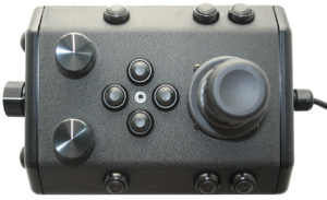
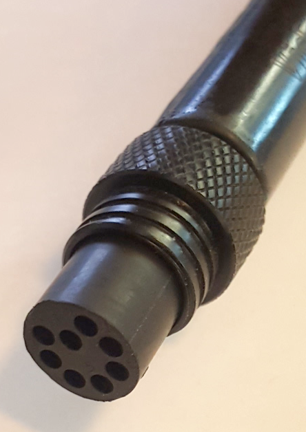
ROV ConnectionsThe Mission Specialist ROV system uses 3 types of connectors for power and communications between the control panel, vehicle modules and accessories. 8 Pin Tether Connector
Pin numbering starts at 1 for the offset pin and is clockwise on the male connector and counter clockwise on the female connector. 5 Pin Thrusters and Lights Connector
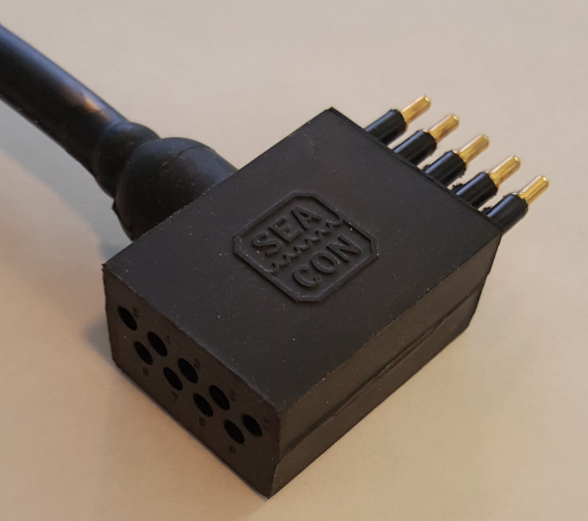
Pin numbering is clockwise starting at 1 in the upper left when looking at the face of the male connector with the row of 3 pins on top. 9 Pin Accessory Connector
Pin numbering is clockwise starting at 1 in the upper left when looking at the face of the male connector with the row of 5 pins on top. |
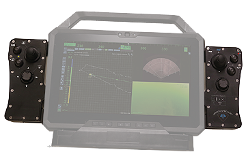
MSS Defender
Operator's Manual
Operator's Manual