Standard Operating Procedures for a Wide Area Search
Using the VideoRay Defender
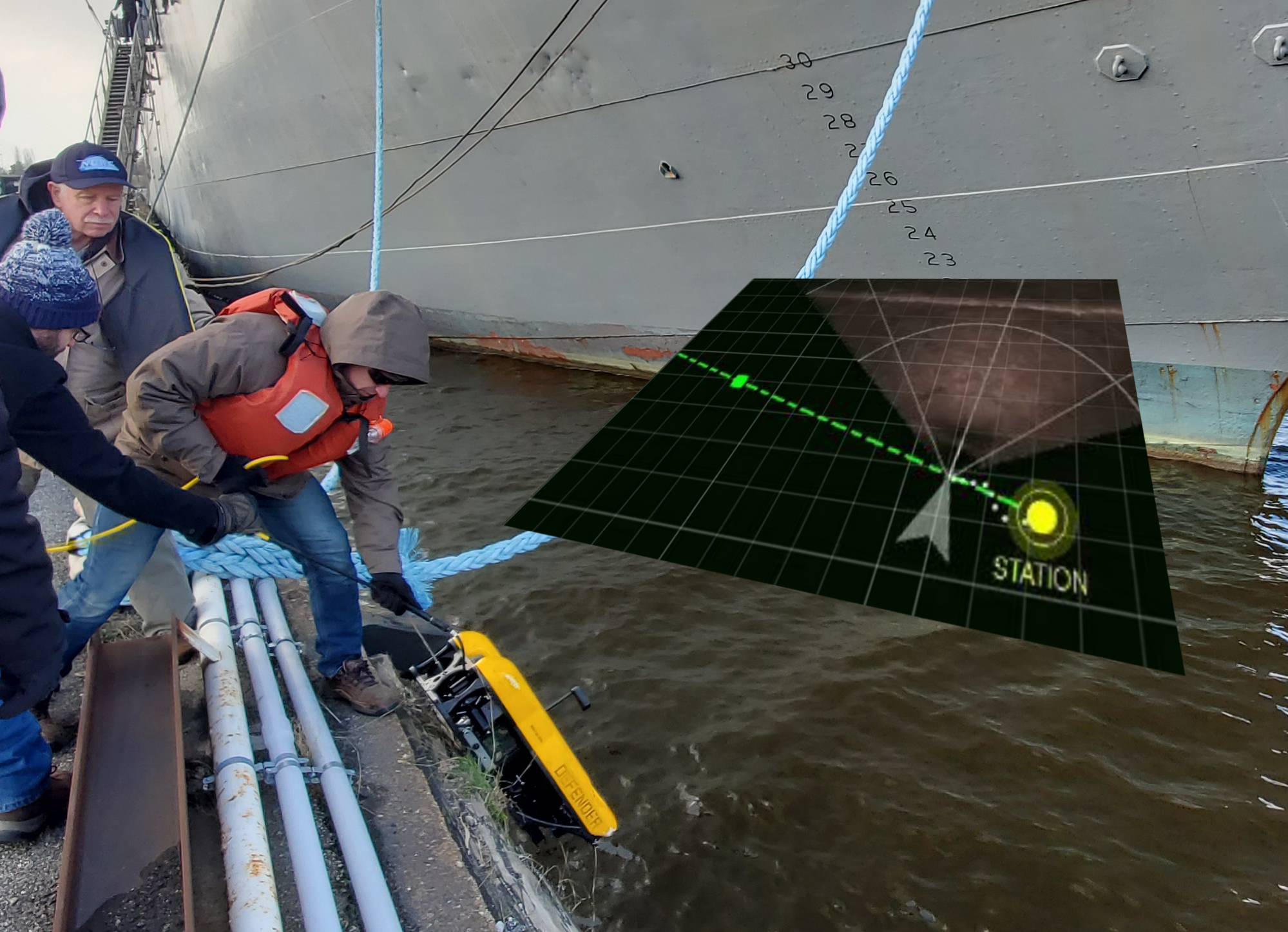
Background image by Alex Messenger
Background image by Alex Messenger

|
Pier Wall Inspection (PWI)
Standard Operating Procedures, 1.00.00 |
|
Background image by Tom Glebas |
|
|
Pier Wall Inspection (PWI)
Standard Operating Procedures, 1.00.00 |
Copyright NoticeThis material is copyright protected. No material may be reproduced or transmitted in any form or by any means for any purpose without expressed written consent of VideoRay LLC. Copyright © 2022, VideoRay LLC - The Global Leader in Micro-ROV Technology |
Language Support
|
Table of Contents |
About this DocumentDocument NavigationYou can navigate through the documentation to specific topics using the menu, or step through sequentially using the Next and Previous arrowhead buttons. The Next button will step you from the current topic to the next topic at the same level unless the current topic has a sub-topic. If the current topic has a sub-topic, the Next button will step you into the first sub-topic. The Previous button works similarly, but in reverse sequence. Your current location within the document is shown as a "breadcrumb" trail at the top of each page under the document title. You can click on any level of the breadcrumb hierarchy to go that location. You can also use the following keyboard shortcuts:
Links are shown in brown font. Finding InformationThis document includes a Table of Contents, Glossary / Index and Google search on each page. You must be connected to the Internet in order to be able to use the Google search, and you can select whether to search VideoRay's online document library only (the default) or the Internet. Document ConventionsSeveral symbols are used throughout this documentation to add emphasis and to assist in relocating important information. The following table describes these symbols and their uses.
Document Customization - My_Notes
Beyond this DocumentThere is no substitute for experience and/or training, especially with respect to the real purpose for which you plan to use this equipment. We encourage you to explore options beyond the scope of these materials to expand your knowledge and skills necessary to support your applications. In addition to this documentation, VideoRay offers training and technical support and hosts a general user discussion forum and user image gallery. We also realize that collectively, users of our products spend considerably more time operating our systems than we do ourselves. Users also encounter more diverse operating environments across an extremely broad range of applications. We highly value this vast experience base, and invite and encourage you to share your experiences and suggestions with us. Please feel free to contact us by any of the methods listed below. Quality CommitmentVideoRay strives to design, manufacture, deliver and support the highest quality products and services, including this documentation. We have made every effort to ensure that this documentation is accurate and provides you with the most up-to-date information. If you find any errors in this documentation or have suggestions for improvements, each page contains a "Help us improve this document" feedback link in the left margin (you must be connected to the Internet to use this link).
DisclaimerThis document is deemed accurate at the time of its writing, however it is not a legal contract and the information contained herein should not be construed to represent any form of commitment. This document as well as the associated products and services are subject to change without notice. Alternate FormatsSingle HTML Page Format Portable / Printable Format HTML File Set |
Customize this Documentation - My_NotesMy_Notes are easy to incorporate directly into the pages of this manual. They can be used to clarify content, add additional information, or document your custom settings, operational tactics or procedures. My_Notes are page specific and display at the bottom of the desired page under the "My_Notes" heading. No programming is required - it is as simple as saving a file with your notes. Creating My_NotesMy_Notes can be written in HTML or plain text. HTML allows for more flexible formatting and inclusion of images or links to other web pages. To add a My_Note, create an HTML or text file containing the note and save it in the VideoRay\My_Notes\ folder, which can be found in the computer account user's documents folder (Documents\ for Windows 7, or My Documents\ for Windows XP). The file should be named the same as the page in which you want the note to appear, with a "my_" prefix (without the quotes). For example, if you want a My_Note to appear at the bottom of this page, the name of the file to create is: my_custom_my_notes.html. The name of the page being viewed can be found in the address bar of the browser being used to display this documentation.
Viewing My_NotesWhen you reload the page, your My_Note will appear - there is nothing else to install or configure. A sample My_Note file has been included to display the My_Note below. You can use this file as a model for creating your own My_Notes. Updating My_NotesTo update a My_Note, simply edit and re-save the My_Note file. Removing My_NotesMy_Notes can be removed by deleting or renaming the My_Note file. Sizing My_Notes Display (Optional)The default vertical size for My_Notes is set to 200 pixels, which is used for the sample My_Note below. Due to browser limitations, My-Notes do not size dynamically. This means that a long My_Note may display a scroll bar in order to view the whole My-Note. You can adjust the size to eliminate the need for the scroll bar. To set the size of a My_Note, you need to edit the file named "my_notes_size_table.js" in the My_Notes\ folder (location defined above). The file contains one line for each page of this document using the following format: window.page_name = size_in_pixels; Find the line for the page that includes the My_Note you want to resize and replace the value of size_in_pixels with the desired size in pixels. The page names are listed alphabetically. Example line from the "my_notes_size_table.js" file for this page: window.custom_my_notes = 200;
|
|
|
Pier Wall Inspection (PWI)
Standard Operating Procedures, 1.00.00 |
How to Get HelpHelp for your Pier Wall Inspection (PWI) is available through several channels. All Hours Self-Service / Crowd-Source Tools
Global Support
Regional Support
Training
Operational Strategies and Tactics SupportIf you need help understanding how to apply your system to a specific project, contact VideoRay or you local VideoRay dealer. We can provide guidance or help you find a certified consultant. |
Before Contacting SupportPlease make sure to consider the following information before contacting VideoRay's Technical Support to report a problem. The following information should available:
Once you have collected the recommended information, visit the "How to Get Help" page for contact information. In addition, please review VideoRay's Support website for additional information about:
|
|
|
Pier Wall Inspection (PWI)
Standard Operating Procedures, 1.00.00 |
Pier Wall Inspection (PWI) OverviewThe Pier Wall Inspection operation is a technique that can be used to visually inspect or search a pier wall structure. The purpose for this procedure is to maximize the chances of success and ensure that the entire pier is systematically inspected so there is no question that the entire pier has been completely inspected or searched. The recommendations for this SOP come from some of the world's leading experts in the field and have been formulated after many hours of field experience. However, they should be considered a starting point since every possible scenario cannot be anticipated. Be prepared to make adjustments and fine tune the settings to adapt these recommendations to your specific circumstances and environment. General ConceptThe Pier Wall Inspection consists of navigating transects or passes parallel to the pier while observing the pier visually or with sonar. Horizontal passes are recommended over vertical passes because placing waypoints for vertical passes is more complicated. ApplicabilityThe Pier Wall Inspection is applicable to solid wall piers, such as concrete or sheet piling piers. Piers that consist of pilings only should be searched using the Piling Pier Inspection Standard Operating Procedure. PrerequisitesParticipants in a Pier Wall Inspection should be familiar with operating a VideoRay Defender running the Greensea Workspace control system. For more information about these products, see the Education Resources Library. Searching for Threats or HazardsIf conducting a Pier Wall Inspection for the purpose of ensuring there are no threats or hazards in the pier area, it may be required to clear an area on the bottom in front of the pier. If the area of concern is close to the pier, a single pass focused on the bottom may be sufficient. If a larger area in front of the pier must be cleared, consider using the Wide Area Search Standard Operating Procedure to complete this part of the search. There are two schools of thought about which part to search first, the pier or the bottom.
|
Working without a ChartIf you do not have a chart of the area showing the pier, you can place waypoints by moving the ROV to the starting and ending points of the section of pier to be inspected. Navigate the ROV to the starting point, and place a waypoint at the ROV's location on the Map View. Then move the ROV to the ending point and and place a seceond waypoint at the ROV's location on the Map View. |
|
|
Pier Wall Inspection (PWI)
Standard Operating Procedures, 1.00.00 |
Pier Wall Inspection (PWI) Step-by-StepThe following pages provide step-by-step instructions for conducting a Pier Wall Inspection (PWI). These steps should be completed in the order presented. The settings recommended provide a starting point, but may need to be adjusted depending on the scenario and conditions. There is an abbreviated summary of these steps in checklist form at the end of this document. The checklist can be printed for use in the field. |
|
1 Mission Planning Preparing for a visual Pier Wall Inspection includes gathering information, defining the area to be covered and deciding on various settings to be used while conducting the inspection. The area to be inspected and the settings can easily be changed during the inspection, but it is a good idea to use the recommendations that follow as a starting point. The steps included in this section are specific to this standard operating procedure and do not include other more general aspects of mission planning such as crew assignments and roles, logistics and supplies, transportation to and from the site, etc. See the Defender Operator's Manual for more information and recommendations.
|
|
1.1 Download or Create a Chart A pier wall inspection is best planned and conducted using a chart.  If you are conducting a Pier Wall Inspection and do not have a chart or do not plan to use one, you can skip this and the next section about loading the chart and continue at step: 1.3 - Set Up the Video Overlay. If you are conducting a Pier Wall Inspection and do not have a chart or do not plan to use one, you can skip this and the next section about loading the chart and continue at step: 1.3 - Set Up the Video Overlay.
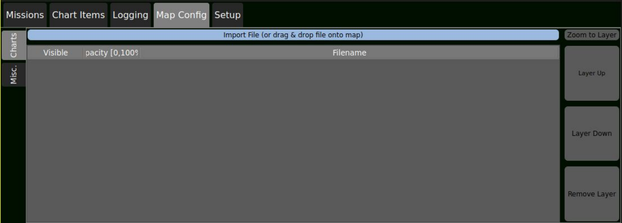
There are several programs and online services for obtaining charts for various locations around the world. Some are available for free and other sources charge fees. Alternatively, Google Earth and SAT2CHART can be used to create charts as needed at no cost. For more information about these options, see: Creating and Using Charts
Once a chart is obtained, it will need to be copied to the operator control console. There is a charts folder in the home folder of the operator control console. When archiving the project, it is a good idea to copy any charts used for the project into the archive for that project.
|
|
1.2 Load the Chart After obtaining a chart and copying it to the operator control console, the chart can be loaded into Greensea Workspace. There are two ways the chart can be loaded. Both methods require that Greensea Workspace is running and the Map view is visible.
|
|
1.3 Set Up the Video Overlay as Desired The video overlay can be used to add valuable information to the permanent record about an operation. Consider adding notes about the project name, location, participants, and if the operation requires multiple dives, identifying each dive with a sequence number, etc. To open the Video Overlay controls, click on the Stethoscope Diagnostics button and then select the Vehicle Configuration tab.
|
|
1.4 Define the Parameters for the Inspection Each mission will require an analysis of the requirements and determination of the appropriate settings to use during the inspection to achieve the objectives. The following information will be relevant to conducting the inspection.
Recommended Settings:
These settings can be made during the steps that follow for setting the Waypoint Defaults and placing waypoints. The above guidelines are recommended starting points and can be modified as appropriate for the operation.
|
|
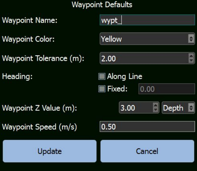
1.5 Set Up the Waypoint Defaults In preparation for placing the waypoints that will define the inspection pattern for the ROV to follow, it is important to set up the defaults that will be applied to each waypoint.
Recommended Settings
|
|
1.6 Place a Minimum of Two Waypoints If you do not plan to use a chart, you will need to place the waypoints in the field. You can skip this step and continue at step 2 - On Site Operations.
Using the chart as a reference, place a waypoint at the beginning of the extents of the pier wall to be inspected and a second at the end of the extents of the section to be inspected. The distance from the pier wall will depend upon the expected visibility as previously noted. This distance is not critical and is just a starting reference at this point. The actual operational distance can be adjusted in the field based on the observed conditions.
|
|
1.7 Save the Mission Plan
To save the mission, make sure the Map view is visible and select the Missions tab -> Missions subtab. Click on the Save button.
|
|
2 On-site Operations This section provides information for setting up and conducting the Pier Wall Inspection (PWI). Before transiting to the site, make sure you have completed your logistics and equipment checklists. |
|
2.1 Site Selection and Set Up The first priority for the site selection and set up should be safety. Ensure that the area and selected location for the operator control console, operator seating, power source, tether deployment path and launch site are risk and hazard free. If possible, set up the operator control console so that the operator is not looking into the sun or has the sun at his or her back. The operator should also wear dark clothing to prevent bright reflections in the monitor. A hat with a brim can reduce glare and the operator control console sunshade can be used to enhance the image quality compared to operating in direct sunlight. Logistics supplies like pop-up tents for shelter from the sun or rain and amenities like drinking water are good to have on hand. Special considerations may be needed if operating from a vessel. These may include:
|
|
2.1.1 Begin the Predive Checklist up through the Functions Tests Start the Pre-Dive checklist and complete it through the functions test.
|
|
2.1.2 Initialize the Recording Before launching the vehicle, record a short video clip of the location and crew. This can be stored with the project and used like a movie clapper to provide quick reference information about the operation. You only need to record a few seconds or you can allow the recording to continue to run. If you want, you can create a movie clapper and use it as well. Experience has shown that most underwater video footage looks similar and when viewed later, it is hard to determine which operation it was from the video alone. |
|
2.1.3 Launch the Vehicle and Complete the Predive Checklist Compete the remainder of the predive checklist, launching and stabilizing the vehicle and initializing the navigation by setting the location and declination.
Place a Home Waypoint at the location of the vehicle for easier navigation back to the launch site at the end of the mission. Use the waypoint defaults first or edit the waypoint to set depth to 0 after placing it).
|
|
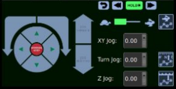
2.2 Open the Mission Controls Open the mission / jog controls so that you are ready to control the vehicle during the mission. This will allow you to make adjustments to the operating parameters easily while maintaining your focus on monitoring the sonar or video and investigating targets.
Set the Waypoint Locks as desired:
All three locks should typically be set to Locked (green). |
|
2.3 Start the Recording If you have not allowed the short initial video clip to continue recording, start the recording! This is critical, but with all of the activities going on, it is very easy to accidentally overlook this. There is a saying in the ROV world, "If you don't have pictures, it didn't happen." |
|
2.4 Conduct the Inspection After you have launched and stabilized the vehicle, there are several settings that you should double-check before immediately starting the mission. These steps ensure that you have enabled recording, the system is ready to go, and your settings are appropriate now that you are on-site and can assess the actual conditions. The following items should be double-checked to ensure they are set or in the case of DVL Lock, that it is active.
|
|
2.4.1 Start the Mission Ensure the path from the vehicle's position to the first waypoint is not obstructed. If it is obstructed, navigate the vehicle to a location that avoids the obstruction and has a clear path to the first waypoint. To start the mission, Right-click on the desired waypoint and select Go to Waypoint.
|
|
2.4.2 Fine Tune the Settings as Appropriate When the mission starts and before you begin your first pass, you should make sure the settings are appropriate for the conditions. Critical aspects to check include the sonar or visual range, the altitude, the pitch and camera angle. Make sure all of these are set satisfactorily to ensure good imagery and good overlap to maximize the ability to conduct a thorough inspection. If they are not satisfactory, now is the time to make adjustments to the path or settings. |
|
2.4.3 Monitor the Sensors While running passes, your job should be monitoring the video looking for areas or targets of interest with a side job of ensuring the vehicle remains on course and does not run into an unforeseen obstruction. In general, the vehicle will navigate itself from waypoint to waypoint so you can focus as much as possible on reviewing the data being provided by the sensors.
|
|
2.4.4 Evaluate Sensor Data for the Objectives If you see something of interest or need to take a closer look at a target during the mission, you have various controls at your disposal. Use these controls to observe targets of interest in more detail, up close or for longer periods of time.
|
|
2.4.4.1 Looking for an Object If an area of interest is found, you should set an MOB point (Marking the ROV's position, heading, attitude and depth) and mark the target with a Marker and take a snapshot. This will provide some redundancy and if you lose sight of the target, you can navigate back to the point where you know you were able to observe it before. "A bird in the hand is worth two in the bush." It is usually best to inspect and identify possible targets when they are first observed rather than to mark numerous targets and wait until the end of the mission to go back to review them. You can easily restart the mission where you left off or by right-clicking on any waypoint and selecting Go to Waypoint or by clicking on the Skip button.
|
|
2.4.4.2 Mapping an Area There are many purposes for mapping an area. In general, the purpose is to develop a point plot of objects of interest or define regions and their associated perimeters for some type of habitat or physical characteristics within the area. Markers can be used to define both. Snapshots that include video and sonar data should be taken frequently. These can be geolocated based on the coordinates on the map view or in the video overlay, which can be included in the snapshot. Additional data such as temperature / location can be extracted using the CSV Export feature. This information can be used to map thermoclines or create contour maps. |
|
2.4.5 Complete Additional Passes At the end of the first pass, the Hold button should become enabled and the mission will stop. At this point, adjust the depth to the planned depth of the next pass. Make sure the Mission Depth Lock is unlocked. Right click on the original waypoint and select "Go to Waypoint." The mission will begin again and progress through the second pass in the reverse direction from the first pass.
Elevation View Continue to alternate passes in each direction by adjusting the depth for each pass and then rerunning the mission back and forth between the end waypoints. |
|
3 Vehicle Recovery At the conclusion of the Pier Wall Inspection (PWI) operation, the vehicle should be piloted to the launch site and recovered. Following the standard Post Dive Operations is recommended. |
|
3.1 Return to the Launch Site At the conclusion of the operation, the ROV should be navigated to the launch site.
If a Home Waypoint was not placed, you can add a Waypoint at the launch location or navigate the ROV home manually.
|
|
3.2 Stop the Recording The recording should be stopped before shutting down the operator control console to ensure the recorded files are closed properly on the disk. If the program is stopped while recording is in progress, the files can become corrupt and unusable. |
|
3.3 Save the Mission After the mission is completed the mission should be saved. This will ensure that all of the added Waypoints, Markers, MOB points and other data entered will be stored as part of the data set for the project. |
|
3.4 Recover the Vehicle Recover the vehicle and complete the standard post dive procedures.
Make sure to clean the vehicle on site or as soon as possible after you have returned to your home base. |
|
4 Post Mission Activities for post mission operations may vary depending on the requirements. Collected data may need to be analyzed and archived. |
|
4.1 Analyze the Data In searches where an object is found, data analysis may not be required. In other situations, it may be necessary to review the data to prepare for the next day's operation, or for area clearing and mapping applications. Analysis may include measuring and identifying sonar targets, georeferencing target locations or reviewing video data. Example of Using Post Mission Data Analysis SuccessfullyWhile exploring a shipwreck at 300 m (1,000 ft), an ROV became entangled on the wreck. A recovery dive was attempted using another ROV, but the trapped ROV could not be located. The sonar from the original dive was then carefully reviewed and a hand drawn mosaic map was created from the sonar imagery including the location of the trapped ROV on the wreck.
Using this ad hoc map of the ship, the second recovery dive was successful at finding and retrieving the trapped ROV. The success was attributed to the ability to use the reference map to identify the location of the recovery ROV relative to the wreck and then navigating to find the trapped ROV. |
|
4.2 Archive the Data Data collected during the operation should be removed from the Operator Control Console on a regular basis (preferably after each mission) by using a network connection or flash drive and the files should be stored in a project folder on a server or copied to a permanent storage media for archival purposes. The files to archive include:
|
|
|
Pier Wall Inspection (PWI)
Standard Operating Procedures, 1.00.00 |
Pier Wall Inspection Checklist
[ Print this checklist
|
| 1 | Mission Planning | |
|---|---|---|
| 1.1 | Obtain a Chart
|
|
| 1.2 | Load the Chart
|
|
| 1.3 | Set Up Video Overlay | |
| 1.4 | Define Inspection Parameters
|
|
| 1.5 | Set Waypoint Defaults
|
|
| 1.6 | Place Waypoints
|
|
| 1.7 | Save the Mission Plan | |
| 2 | On-site Operations | |
| 2.1 | Site Selection and Set Up | |
| 2.1.1 | Begin the Predive Checklist | |
| 2.1.2 | Initialize the Recording | |
| 2.1.3 | Launch the Vehicle | |
| 2.2 | Open Mission Controls
|
|
| 2.3 | Start the Recording | |
| 2.4 | Conduct the Inspection
|
|
| 2.4.1 | Start the Mission
|
|
| 2.4.2 | Fine Tune Settings
|
|
| 2.4.3 | Monitor the Sensors | |
| 2.4.4 | Evaluate for Objectives
|
|
| 2.4.4.1 | Looking for an Object | |
| 2.4.4.2 | Mapping an Area | |
| 2.4.5 | Complete Additional Passes
|
|
| 3 | Vehicle Recovery | |
| 3.1 | Return to Launch Site | |
| 3.2 | Stop the Recording | |
| 3.3 | Save the Mission | |
| 3.4 | Recover the Vehicle | |
| 4 | Post Mission | |
| 4.1 | Analyze the Data | |
| 4.2 | Archive the Data |