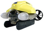
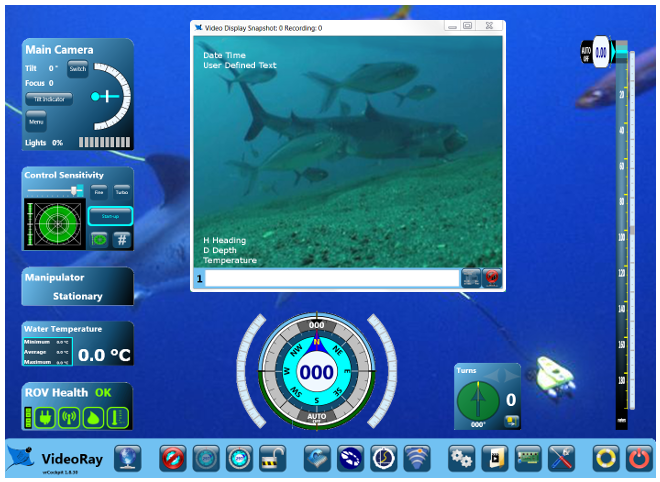
Switches and Connections
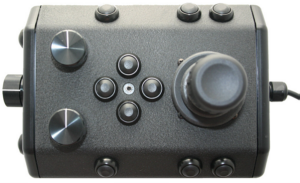
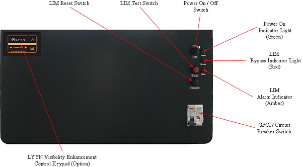
Control Panel Top
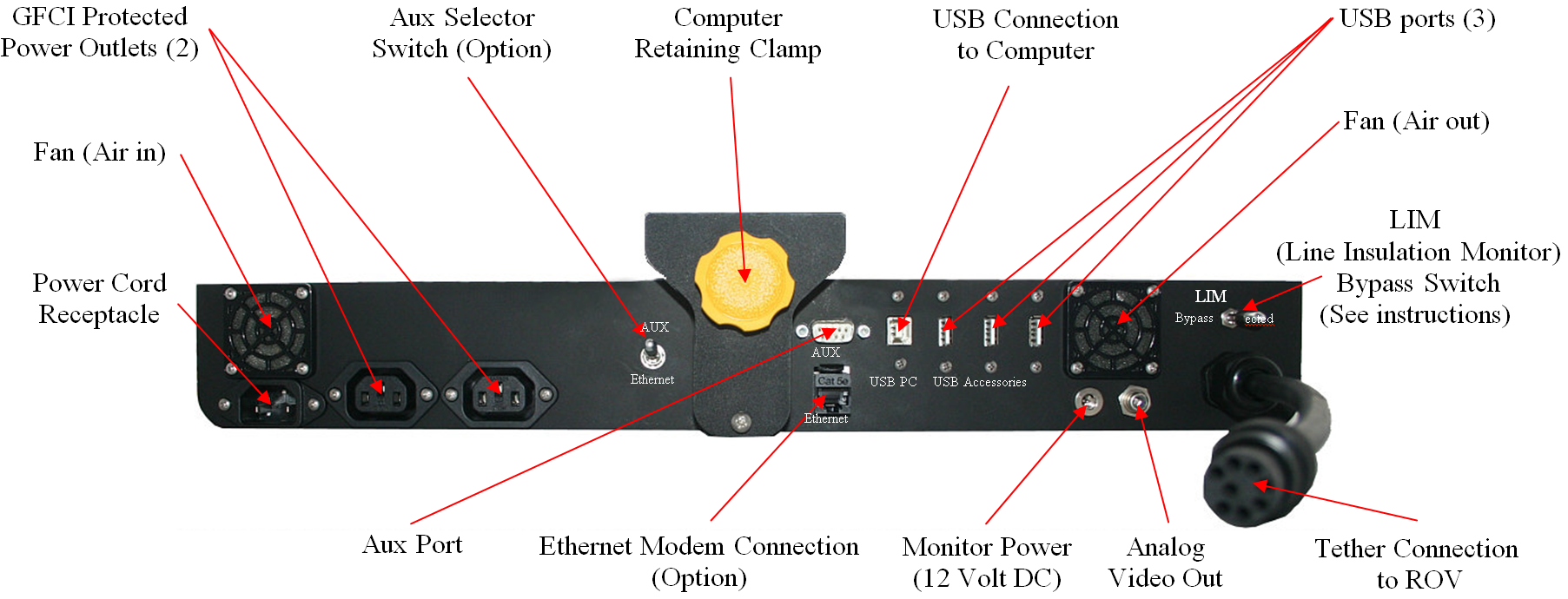
Control Panel Rear
The control panel includes the following switches:
|
SWITCH
|
LOCATION
|
FUNCTION
|
|
GFCI/Circuit Breaker
|
In-line with the power cord
|
Turns on the power outlet and enables the power switch.
|
|
Power
|
Control panel top
|
Turns the control panel on.
|
The control panel includes the following connections:
|
CONNECTION
|
TYPE
|
FUNCTION
|
|
Power (100-240 Volts AC, 50, 60 Hz)
|
IEC male
|
Used to connect the control panel to a power source.
|
|
GFCI/Circuit Breaker Protected Power Outlet
|
IEC female
|
Used to connect the computer and another device to the control panel to receive power.
|
|
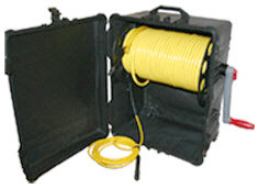
Tether Whip (Specifications)
|
8 pin round female
|
Used to connect the control panel to the tether for power, communications, video and accessory support.
|
USB PC
|
Type B female
|
Used to connect the control panel to the computer.
|
|
USB Accessory pass through
|
Type A male
|
Can be used to connect USB devices to the computer via the control panel.
|
|
AUX Port (Specifications listed below)
|
DB-9 male
|
Provides access the APIC (Auxiliary Pair of Independent Conductors) in the tether. Can be used with ROV accessories that need to rely on the APIC for communications.
|
AUX Port Specifications
|
PIN
|
FUNCTION
|
|
1
|
No connection
|
|
2
|
No connection
|
|
3
|
No connection
|
|
4
|
No connection
|
|
5
|
No connection
|
|
6
|
No connection
|
|
7
|
AUX + (Connects to tether pin 4 and ROV accessory port pin 4)
|
|
8
|
AUX - (Connects to tether pin 6 and ROV accessory port pin 6)
|
|
9
|
No Connection
|
Connector Type - DB-9 Male.
 The AUX Port provides access to the APIC. Some accessories use the AUX port directly and the topside device requires a female DB-9 connector. Some accessory interfaces can be built into the control panel. For control panels that have built-in accessory interfaces, there is a switch on the back of the control panel that determines whether the APIC is connected to the AUX port, or to the accessory interface inside the control panel. The switch must be set to the proper position depending upon whether you want to use an external device or the built-in accessory interface. Set the switch to AUX if you want to use an external accessory device on the topside. Set the switch to the correct setting for any built-in accessory device that you want to use. For built-in accessories, there is either another dedicated connector (to connect to the laptop), or the accessory might use USB (to connect to the laptop), in which case a separate connector is not necessary. See the instructions that come with each accessory for more information. The AUX Port provides access to the APIC. Some accessories use the AUX port directly and the topside device requires a female DB-9 connector. Some accessory interfaces can be built into the control panel. For control panels that have built-in accessory interfaces, there is a switch on the back of the control panel that determines whether the APIC is connected to the AUX port, or to the accessory interface inside the control panel. The switch must be set to the proper position depending upon whether you want to use an external device or the built-in accessory interface. Set the switch to AUX if you want to use an external accessory device on the topside. Set the switch to the correct setting for any built-in accessory device that you want to use. For built-in accessories, there is either another dedicated connector (to connect to the laptop), or the accessory might use USB (to connect to the laptop), in which case a separate connector is not necessary. See the instructions that come with each accessory for more information.
|