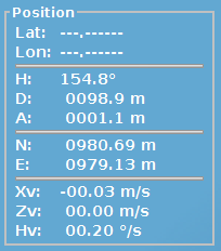
6 - Pilot Display InformationThe pilot information display contains the essential navigation information required to operate the ROV with confidence and precision. This display provides the user with the current navigation data for the ROV and a visible indication of the selected flight control method. The pilot information display comprises many user-friendly elements, including the current navigation information; status indicators; and flight mode and velocity selection. 6.1 Navigation InformationThis navigation information panel provides the user with the following ROV information: heading (H), depth (D) and altitude (A). This information is normally updated from the navigation system, but if the DP is in standby only the raw ROV information is displayed. No value is displayed if no ROV information is detected.
Figure 4 - Navigation Information 6.2 Status IndicatorsThe status indicators on the pilot information display allow the user to monitor the status of the ROV.
Figure 5 - Status Indicators 6.2.1 The DP Status IndicatorThis indicator displays the status of the DP system: The indicator is green when the DP system is running.
Figure 6 - DP System Running The indicator is red when the DP system is in standby.
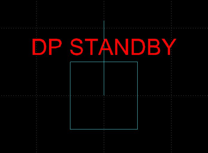
Figure 7 - DP System Standby The DP can go into standby if the ROV is not in working range (i.e. the DVL has no bottom-lock) or some critical error was detected. In this situation VideoRay CoPilot changes into MANUAL mode and the pilot has full control.
Figure 8 - DP Standby Display 6.2.2 The Position Status IndicatorThis indicator is illuminated when the ROV is within the tolerance range of its target position. The indicator is not displayed when the ROV is not in position.
Figure 9 - Position Status Indicator 6.2.3 The Joystick IndicatorThis indicator is displayed when the system receives a command from the joystick. The indicator is not displayed when the joystick is not considered to be in use. If the joystick movement is within the specified deadband range, the system will not detect the command. For example, a joystick movement of 20% will not be detected by the system if the deadband setting is 30%.
Figure10 - Joystick Indicator 6.2.4 The Navigation Status IndicatorThis indicator can have four different displays, depending on the accuracy of navigation system and the ROV's global reference:
6.2.5 The DVL Lock IndicatorThis indicator informs the user of the failure of the DVL sensor to get an adequate fix on the seabed. When this indicator is illuminated the DP system will lose precision after a short amount of time. The ROV can be flown in MANUAL mode under these circumstances. When the DVL gets a fix on the seabed, the indicator is not shown and the system will return to normal operation.
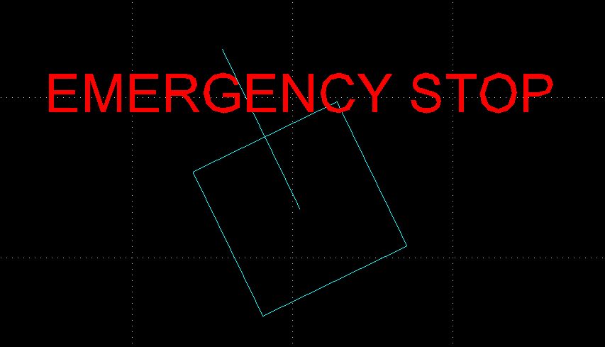
Figure 15 - DVL Lock Indicator 6.2.6 The Emergency Stop IndicatorThis indicator is displayed when the user has pressed the remote "Eemergency stop" button. "EMERGENCY STOP" will be shown in the navigation chart display, as shown below, and the ROV will go into MANUAL mode.
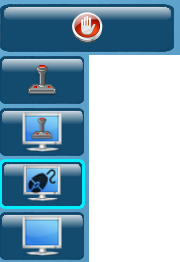
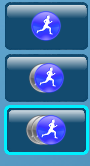
Figure 16 - Emergency Stop Indicator 6.3 Flight ModesSelecting the flight mode buttons on the pilot information display changes the flight mode and the active button is highlighted with a blue outline.
Figure 17 - Flight Modes
6.3.1 HOVER CommandThe ROV maintains position when the "HOVER" button is selected. The HOVER command can be used at any time to interrupt the vehicle's motion and hold the position of the ROV. The HOVER command provides station-keeping at the touch of a button and is useful for monitoring missions when the ROV must remain in a fixed position for long periods of time.
6.3.2 Flying in MANUAL ModeIn MANUAL mode the pilot has full control as if the joystick is directly connected to the ROV, and the DP system is in standby. The pilot interface displays navigation data and monitors the position of the ROV.
Example:
6.3.4 Flying in AUTOHOVER ModeIn AUTOHOVER mode the pilot has full control as if the joystick were directly connected to the ROV. This mode provides station-keeping when no control inputs from the joystick are detected.
If the pilot releases the joystick, the DP system takes control and maintains the vehicle's position. The pilot can use the joystick again to regain full control of the ROV. Example:
Flying in AUTOFLY ModeIn AUTOFLY mode the DP system is in total control. The ROV can be controlled with both mouse and joystick commands, and when there are no commands the DP system provides station-keeping. AUTOFLY mode also offers the user a range of additional navigation tools to assist in controlling the ROV. These navigation tools allow the user to plan detailed missions for the ROV with ease and precision.
Figure 18 - Navigation Tools 6.3.4.1 Click & Go Navigation Tool Click & Go is the default navigation tool in AUTOFLY mode. The pilot can select a set of coordinates by clicking on the screen using the mouse and the ROV will then fly to those coordinates and go into a stable hover. Alternatively, the ROV can be moved using a joystick input and will decelerate to a stable hover when the joystick is released. This method of station-keeping provides a smoother halting maneuver for the ROV, and is only available in the AUTOFLY flight mode. Example:
Figure 19 - AUTOFLY Speeds
6.3.4.2 Survey Plan Tool The Survey Plan tool is used to prepare a mission for the ROV by either planning a survey or uploading a saved survey. The user can specify the coordinates, depth/altitude and wait time for each of the waypoints in the path before the ROV begins its mission. When activated, the ROV will automatically follow the designated path with no further input from the pilot, unless interruption is deemed necessary. The Survey Plan tool allows the pilot to observe and monitor the ROV and sensors instead of negotiating its path manually. The user can employ two methods to plan a path for the ROV: Planning a Survey Using the Mouse The user must indicate the position for each of the waypoints using the mouse.
The waypoints are assigned an ID number as they are registered on the navigation chart, to remind the user of the order of sequence.
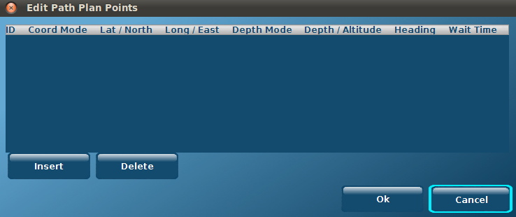
Figure 20 - Path Planning a Survey Using the Editor It is also possible to plan a survey by selecting the "Survey Plan" button and entering the required data manually for the series of waypoints by selecting the "Edit the current path" button.
Figure 21 - Survey Planning To begin planning a survey using the editor, the user must select the "Insert" button. This will produce a line of data detailing the ROV's current position, which the user can then amend to specify the first waypoint for the ROV's path. Additional waypoints can then be added by repeating this process. The user can enter the coordinates for the waypoint in two formats:
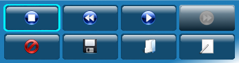
The user also has the option of selecting either depth or altitude mode when specifying the waypoint. The survey will be loaded and displayed on the navigation chart by selecting the "Ok" button. Editing a Survey Whether it was created using the mouse or editor, the user can edit the details of a path by selecting the "Edit the current path" button at the top of their screen. The coordinates, depth/altitude, heading and wait time (in seconds) for a waypoint can all be altered by selecting the appropriate field and entering the required data. It is possible to insert new waypoints within the path by selecting the entry in the table directly after the desired position of the new waypoint, then pressing the "Insert" button. For example, if the user wishes to insert a new waypoint between positions 2 and 3, they should select the entry in the path table with the ID number 3, then select "Insert". This will produce a new entry with coordinates exactly half-way between the waypoints 2 and 3. This data can then be amended according to the particular values of the new waypoint. It is also possible to delete waypoints by first selecting the appropriate entry in the editor table, and then pressing the "Delete" button. Running a Survey To run the mapped survey, the user must select the "Play" button. The ROV will then visit each of the waypoints, before moving on to the next. The "Pause" button can be used to suspend the journey, and the "Stop" button can be used to stop the journey completely. The survey can be removed at any time by selecting the "Clear" button. It is possible to begin the Survey Plan journey at the last numbered waypoint, and visit the numbered positions in descending order, by selecting the "Backward" button instead of the "Play" button. The "Backward" and "Forward" buttons can be used to skip waypoints. When the ROV has completed the Survey Plan sequence, the user can select the "Play" button again to repeat the journey.
Figure 22 - Running a Survey Saving a Survey Plan A Survey can be saved at any point by selecting the "Save" button and entering an appropriate file name and location. Loading a Survey Saved Surveys can be loaded by selecting the "Load" button and opening the appropriate file.
6.3.4.3 Waypoint Navigation Tool The Specific Waypoint navigation tool allows the user to manually send the ROV to a specific position using absolute or relative coordinates. Any incorrect data fields will be highlighted in red and the tool-tip will indicate what is wrong with the user entry when using the navigation tool.
Figure 23 - Waypoint There are three methods of identifying the waypoint:
Figure 24a - Waypoint Navigation, Global Position
Figure 24b - Waypoint Navigation, Local Position
Figure 24c - Waypoint Navigation, Relative Position The user must first select the required method of specifying the waypoint by selecting the appropriate tab at the top of the Waypoint panel. The user must then enter the precise figures for each field according to the chosen method of determining the waypoint. By selecting the "Send" button, the command is activated and the ROV is directed to the specified coordinates.
6.3.5 Flying in CRUISE ModeCRUISE mode is ideal for survey work when the ROV must keep a constant heading and speed irrespective of the currents. In CRUISE mode the DP system is in total control, and the ROV moves in a straight line at a constant depth/altitude, heading and forward velocity. The joystick or mouse can be used at any time to alter the heading, depth/altitude and velocity of the ROV - without interrupting the CRUISE mode. The pilot may also adjust the position of the ROV to an alternative trajectory parallel to the vehicle's current heading using the joystick or a left-button mouse click.
Example:
6.4 Velocity ControlsAs with the flight mode buttons, the Velocity Control buttons serve to change the ROV velocity and indicate the current setting by highlighting the selected button in blue.
Figure 25 - Velocity Controls This velocity setting is only available in AUTOFLY and CRUISE modes. Only X (Surge) is controlled by this setting. 6.5 Alarm PanelThe alarm panel is displayed across the bottom of the pilot interface. It displays the current status of each software component that allows VideoRay CoPilot to run smoothly. If a software component fails, its name is illuminated in the alarm panel situated along the bottom of the pilot interface. In normal operation, the bar illustrated below should have no alarms illuminated, and it will remain invisible to the user until any failure occurs.
Figure 26 - Alarm Panel
|
|||||||||||
|
|


.png)
.png)
.png)

