7 - Additional Interface FunctionsThere are further interface options available to users. These options can be found to the top center, above the pilot interface, and right, above the waterfall, of the interface toolbar. These additional functions include:
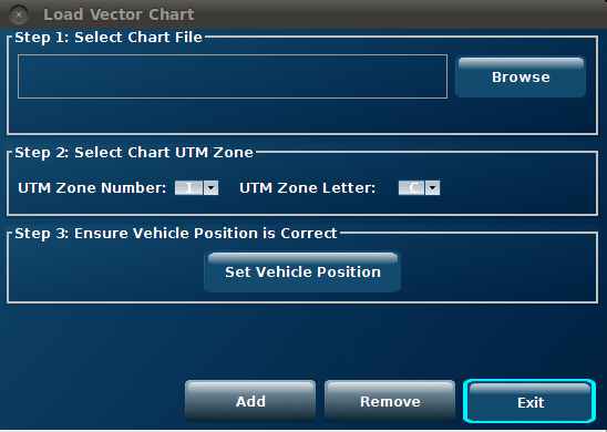
7.1 Chart LoadingThe "Chart Loader" button allows the user to add a vector chart to the navigation chart display. It can only display one chart at a time. The vector chart must be an AutoCAD® 14 DXF file in UTM WGS84 format or an ENC chart and the chart must not exceed the boundaries of the relevant UTM zone.
Figure 33 - Loading a Chart
The Load Vector Chart dialog box comprises three steps:
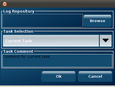
Select the "Add" button to insert the chart on to the navigation chart display. Select the "Exit" button to close the dialog box. Removing a ChartSelecting the "Remove" button removes the current chart displayed in the navigation chart display. If no chart is present, no action is taken. 72. Taking a ScreenshotA screenshot of the current interface display can be taken by selecting the "Screenshot" button. By selecting this button, a screenshot of the current interface display will be captured and saved to the desktop as a bmp. file. 7.3 Log RecordingThe "Log Recording" button allows the user to record a sequence of system activity into a legible file, which can then be stored for future reference or inspection. The file will compile and display details such as navigation information and critical system data. After selecting the "Log Recorder" button, a dialog box requiring details of the log will be shown.
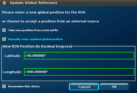
Figure 34 - Log Repository The Log Repository allows the user to browse the system files and folders to find the desired location for the recorded log, which will be saved as a .CSV file. The Task Selection drop-down list allows the user to enter the title of the log. There is also the option to include a Task Comment by entering the appropriate text into the box provided. After selecting the "Ok" button the system will begin to record the system activity to the specified file. The process can be stopped, and the log completed, at any time by re-selecting the "Log Recorder" button. 7.4 External Position FixBy selecting the Change Vehicle Position menu item, the user is presented with two options:
Figure 35 - External Position Fix By checking the "Remember this choice" box before exiting the dialog box, the system will store the details of the request and remember them the next time the user accesses the Change Vehicle Position menu item. 7.5 Clearing the Breadcrumb TrailAs the ROV moves across the Pilot Interface, a breadcrumb trail will be left, highlighting the path of the vehicle. This path can be cleared by simply selecting the "Clear Breadcrumb Trail" button.
7.6 PreferencesThe "Preferences" button can be located on the top right of your screen, above the waterfall. The "Preferences" button will allow users to control:
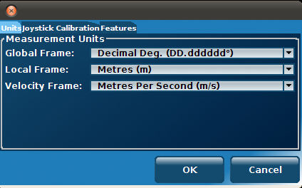
7.6.1 UnitsThe user can change the display measurement (position) units used in the interface to meters or feet. The velocity units can also be changed to m/s, ft/s or knots.
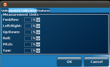
Figure 36 - Units 7.6.2 Joystick CalibrationThis menu item is used to calibrate the joystick that is currently connected to the VideoRay CoPilot system.
After selecting this item, the user can configure the region in which the joystick will be classed as "deadstick"
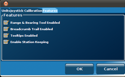
Figure 37 - Joystick 7.6.3 FeaturesThis menu item allows the user to enable or disable the following features:
Figure 38 - Features Each feature can be enabled or disabled by simply clicking on the tick box to the left of the description. A tick indicates the feature is enabled. |
|
|
|