Propeller Maintenance

Propellers are considered wear items and should be inspected before every dive during the Pre-Dive Setup procedures.
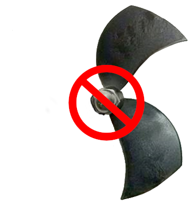
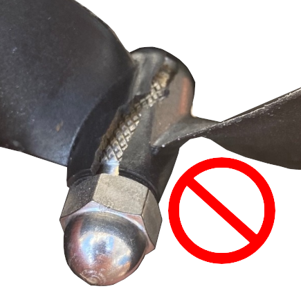
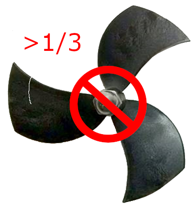
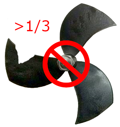
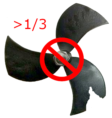
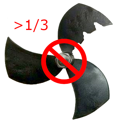
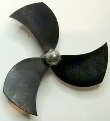
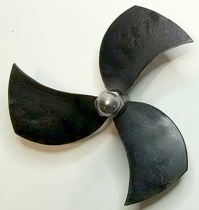
Failed propellers can cause control problems, including loss of the ROV, and should be evaluated during the Pre-Dive Setup or whenever control problems occur.

Propeller Replacement Guidelines

Propeller replacement can be based on a rigid pass/fail criteria, such as when a propeller blade breaks off and is missing, in which case the propeller should be replaced immediately, or based on a risk assessment when the propeller has mild to moderate wear. Such a risk assessment should consider the importance and urgency of the mission. If the mission is critical, deep or it would be difficult to retrieve the ROV in the event of a control failure due to the loss of a propeller, such as operating in a confined space, a propeller that exhibits even mild wear should probably be replaced. If the mission is brief, shallow and there is no risk of difficulty in retrieving the ROV by its tether, then even moderately worn propellers can remain in service.

The following guidelines are provided to help determine whether propellers should be replaced or not.

Propellers should be replaced if any of the following conditions are observed:
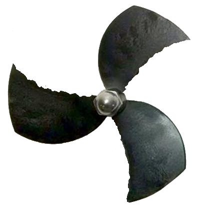
  1. Any propeller that results in poor vehicle performance or control.

  2. Any propeller that is missing one or more blades.

  3. Any propeller that has a crack along the axis of its hub.

    This type of failure may not be as obvious as the others, but it can significantly impact vehicle control. You may need to apply light pressure the propeller blades to expand the crack to make it more visible.

  4. Any propeller with a crack that exceeds 1/3 of the dimension of the blade in the direction of the crack.

  5. Any propeller with a chip or chips when the total width of the chip(s) exceeds 1/3 of the dimension of the blade in depth into the blade or length along the blade's edge.

Generally Acceptable Propeller Wear

Generally, any propeller that has a ragged edge can be used as long as it does not affect vehicle performance or control. Loose pieces or pieces bent out of the plane of the propeller should be removed using sandpaper or a file.

Propellers in this conditions should be inspected more frequently and closer for cracks or other indications that it might fail soon.

Propeller Replacement Procedures

Propellers are connected to the thruster shaft using a drill chuck-like collet that has a fluted tapered core that compresses on the shaft when the propeller nut is tightened.
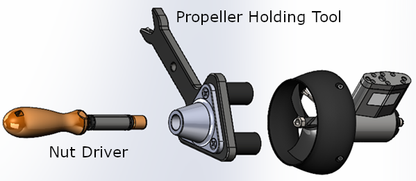
Propeller shafts can be bent or broken if lateral force is applied to the propeller while removing it. Using the propeller holding tool can prevent accidental lateral force from being applied to the shaft during the removal and replacement procedures.

Propeller Removal

To remove a propeller, loosen, but do not remove the nut using the propeller holding tool and 7/16" nut driver. The collet should then be free to slip out of the hub, open and release from the shaft. The propeller can then be pulled off the shaft.

In some cases, the collect can remain stuck in the hub, which prevents the collet from releasing from the shaft. If the collet is stuck on the shaft, these methods might help to free it.

  1. Loosen, but do not remove the nut. Apply pressure to the propeller from the side opposite the nut. Apply a sharp quick rap to the outer tip of the nut using a hard tool. This should pop the hub off the collet and free it from the shaft.

  2. If the above method does not work, soak the propeller in hot water for 15 minutes and then try the rapping technique again.

If the propeller cannot be removed from the shaft, contact VideoRay Support for additional recommendations.

Propeller Replacement

Thrusters are counter-rotating and the correct propeller pitch for the thruster's location must be installed.

See the Thruster Arrangement configuration table for the correct propeller type selection for each thruster.

  • Right-hand propellers can be identified as follows:
    • The top blade has the leading edge on the right when viewed from the end with the nut.
    • The blades appear to curve counterclockwise when viewed from the end with the nut.
    • Right hand propellers have a stainless steel collar on the hub at the shaft end.

  • Left-hand propellers can be identified as follows:
    • The top blade has the leading edge on the left when viewed from the end with the nut.
    • The blades appear to curve clockwise when viewed from the end with the nut.
    • Left hand propellers have hub that is all plastic.

After selecting the correct propeller pitch for its installed location, loosen but do not remove the propeller nut and install the propeller on the thruster shaft until it is seated.

Using the propeller holding tool and 7/16" nut driver, tight the propeller nut. The nut should be tightened as much as possible (assuming a person with average strength) to prevent it from slipping off during operations.

The Pro 4 and Mission Specialist Systems use the same propeller and hub, but the collet and shaft diameter are different. The propeller and hub are interchangeable between Pro 4 and Mission Specialist Systems, but the collet is not.

Mission Specialist Pro 5
Operator's Manual, Version: 1.00.00
Copyright © 2022, VideoRay LLC - The Global Leader in Micro-ROV Technology