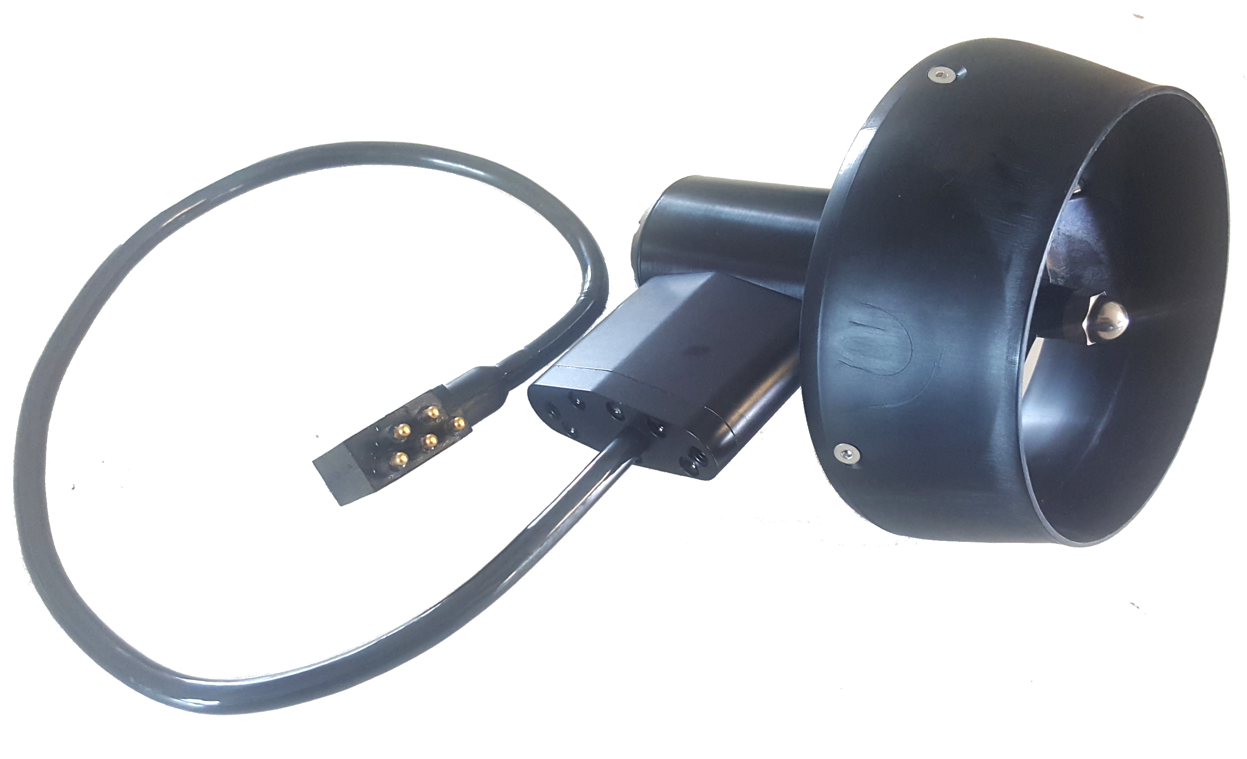
Thruster Module

Mission Specialist vehicles use a modular thruster configuration that allows vehicle designs to be optimized for water conditions and payload delivery requirements. Modular thrusters are also easy to replace in the field.
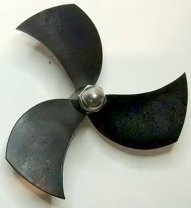
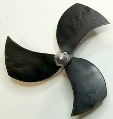
Thruster Propeller

The propellers are designed to be used on counter-rotating thruster arrangements to eliminate torque roll or yaw. Propellers are identified by their pitch orientation using left and right based on their pitch. The convex edge of the propeller blade is the leading edge during motion that is considered forward for that thruster.

  • Right-hand propellers can be identified as follows:
    • The top blade has the leading edge on the right when viewed from the end with the nut.
    • The blades appear to curve counterclockwise when viewed from the end with the nut.
    • Right hand propellers have a stainless steel collar on the hub at the shaft end.

  • Left-hand propellers can be identified as follows:
    • The top blade has the leading edge on the left when viewed from the end with the nut.
    • The blades appear to curve clockwise when viewed from the end with the nut.
    • Left hand propellers have hub that is all plastic.

Cable Pinout

The Thruster connector uses a male / female stackable connector allowing the thrusters and LED lights to be connected in series.

Pin Function Wire AWG Color
1 48 V DC + 20 Red
2 GND 22 Green
3 48 V DC - 20 Black
4 RS-485 A 24 Gray
5 RS-485 B 24 White
Thruster Arrangement

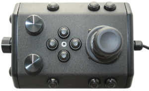
The Pro 5 vehicle is a Defender frame that uses a vectored horizontal thruster arrangement, and three vertical thrusters. The thrusters are configured as shown below:

Thruster Location Group ID Node ID Motor ID Propeller Orientation Reverse Option Maximum Power (Watts) Notes
Starboard 129 5 0 Right Disable 600
Port 129 6 1 Left Enable 600
Vertical 129 7 2 Right Enable 600

Mission Specialist Pro 5
Operator's Manual, Version: 1.00.00
Copyright © 2022, VideoRay LLC - The Global Leader in Micro-ROV Technology