|
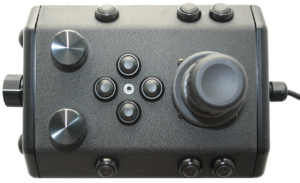
Power / Communications ModuleThe Power Module receives power from the topside and converts it to power levels required by the various modules, sensors and accessories.
8 Pin Male Tether Connector
5 Pin Female High Power (Thruster, Lights) Connector (2)
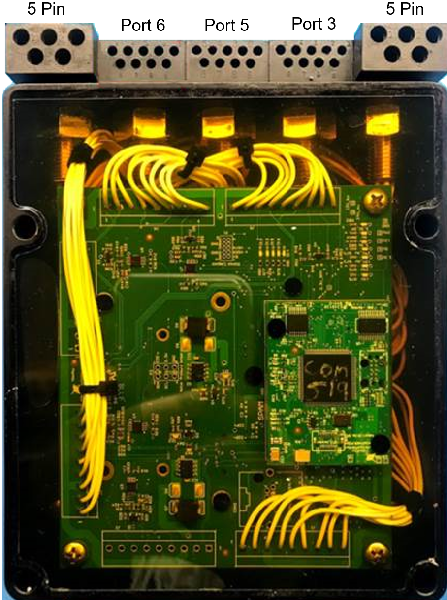
Power is rated at 750 Watts per port for 1,500 Watts total. Power Module ArrangementThe communications module is the "brains" of the vehicle and coordinates vehicle control systems and provides data paths for sensors and accessories. 9 Pin Female Interface Connectors
Power is rated at 300 Watts for the 24 Volt circuit and 120 Watts for the 12 Volt circuit. Communications Module Arrangement |
||||||||||||||||||||||||||||||||||||||||||||||||||||||||||||||
|
[ Help us improve this document ] [ Print this page |
Mission Specialist
Encyclopedia
Encyclopedia