Mission Specialist pro_5 Operator's Manual
|
|
Mission Specialist Pro 5 Operator's Manual, 1.00.00 |
Copyright NoticeThis material is copyright protected. No material may be reproduced or transmitted in any form or by any means for any purpose without expressed written consent of VideoRay LLC. Copyright © 2022, VideoRay LLC - The Global Leader in Micro-ROV Technology |
|
|
Mission Specialist Pro 5 Operator's Manual, 1.00.00 |
|
|
Mission Specialist Pro 5 Operator's Manual, 1.00.00 |
About this DocumentOnline ManualThis printed Quick Start Guide is a subset of the full version of this manual, which is available on the Mission Specialist Pro 5
Document ConventionsSeveral symbols are used throughout this documentation to add emphasis and to assist in relocating important information. The following table describes these symbols and their uses.
Beyond this DocumentThere is no substitute for experience and/or training, especially with respect to the real purpose for which you plan to use this equipment. We encourage you to explore options beyond the scope of these materials to expand your knowledge and skills necessary to support your applications. In addition to this documentation, VideoRay offers training and technical support and hosts a general user discussion forum and user image gallery. We also realize that collectively, users of our products spend considerably more time operating our systems than we do ourselves. Users also encounter more diverse operating environments across an extremely broad range of applications. We highly value this vast experience base, and invite and encourage you to share your experiences and suggestions with us. Please feel free to contact us by any of the methods listed below. Quality CommitmentVideoRay strives to design, manufacture, deliver and support the highest quality products and services, including this documentation. We have made every effort to ensure that this documentation is accurate and provides you with the most up-to-date information. If you find any errors in this documentation or have suggestions for improvements, each page contains a "Help us improve this document" feedback link in the left margin (you must be connected to the Internet to use this link).
DisclaimerThis document is deemed accurate at the time of its writing, however it is not a legal contract and the information contained herein should not be construed to represent any form of commitment. This document as well as the associated products and services are subject to change without notice. |
|
|
Mission Specialist Pro 5 Operator's Manual, 1.00.00 |
How to Get HelpHelp for your Mission Specialist Pro 5 All Hours Self-Service / Crowd-Source Tools
Global Support
Regional Support
Training
Operational Strategies and Tactics SupportIf you need help understanding how to apply your system to a specific project, contact VideoRay or you local VideoRay dealer. We can provide guidance or help you find a certified consultant. |
Before Contacting SupportPlease make sure to consider the following information before contacting VideoRay's Technical Support to report a problem. The following information should available:
Once you have collected the recommended information, visit the "How to Get Help" page for contact information. In addition, please review VideoRay's Support website for additional information about:
|
|
|
Mission Specialist Pro 5 Operator's Manual, 1.00.00 |
Mission Specialist Pro 5 |
|
|
Mission Specialist Pro 5 Operator's Manual, 1.00.00 |
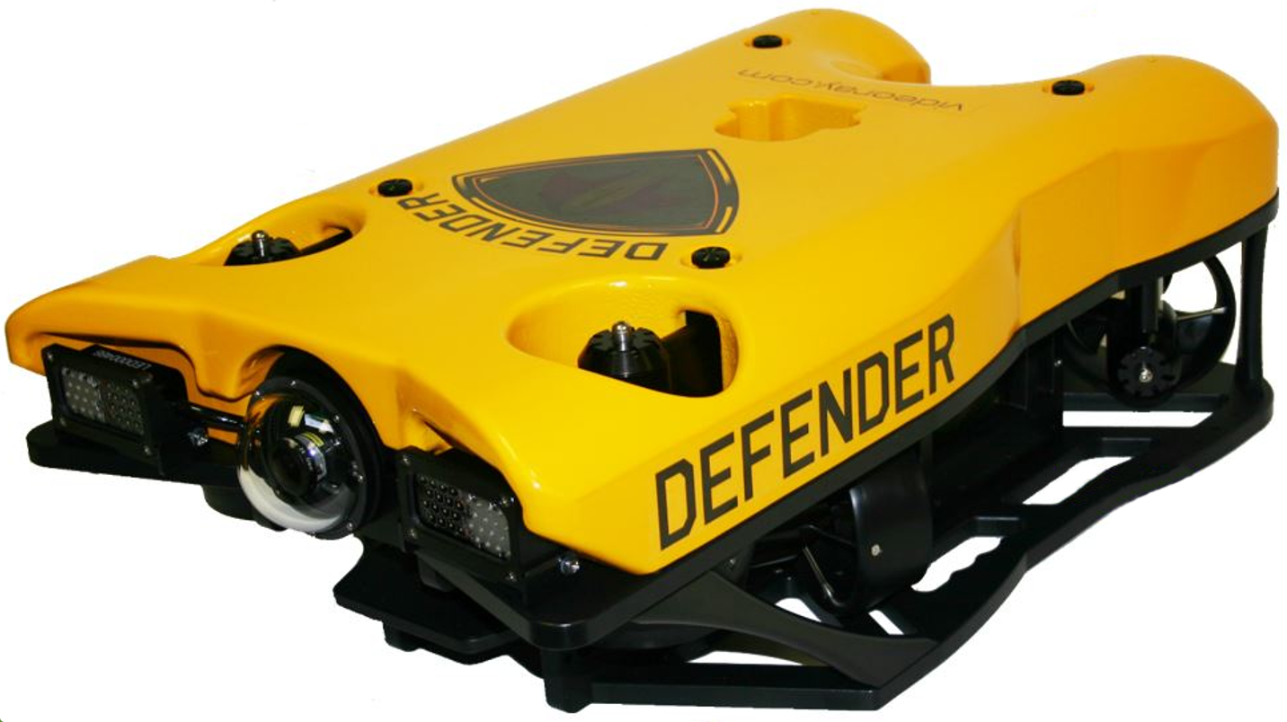
Mission Specialist Vehicle ConfigurationsMission Specialist vehicle configurations include:
The Defender system is designed to use multiple different topside control architectures for different operational needs. See the Operator Control Consoles section for more information about the available topside configurations. Vehicles are shown approximately to scale. |
|
|
Mission Specialist Pro 5 Operator's Manual, 1.00.00 |
Quick Start InstructionsThese Quick Start Instructions are streamlined to cover just the essentials of operating your Mission Specialist Pro 5
The following Quick Reference Sheets are available for the VideoRay Defender: Topics in this Section |
Safety First
How Safe Is Safe Enough?Addressing all aspects of safety while working in a water environment is beyond the scope of this documentation. VideoRay encourages you to participate in safety training appropriate for your industry and applications, including such topics as vessel operations, first aid, survival and other relevant topics. |
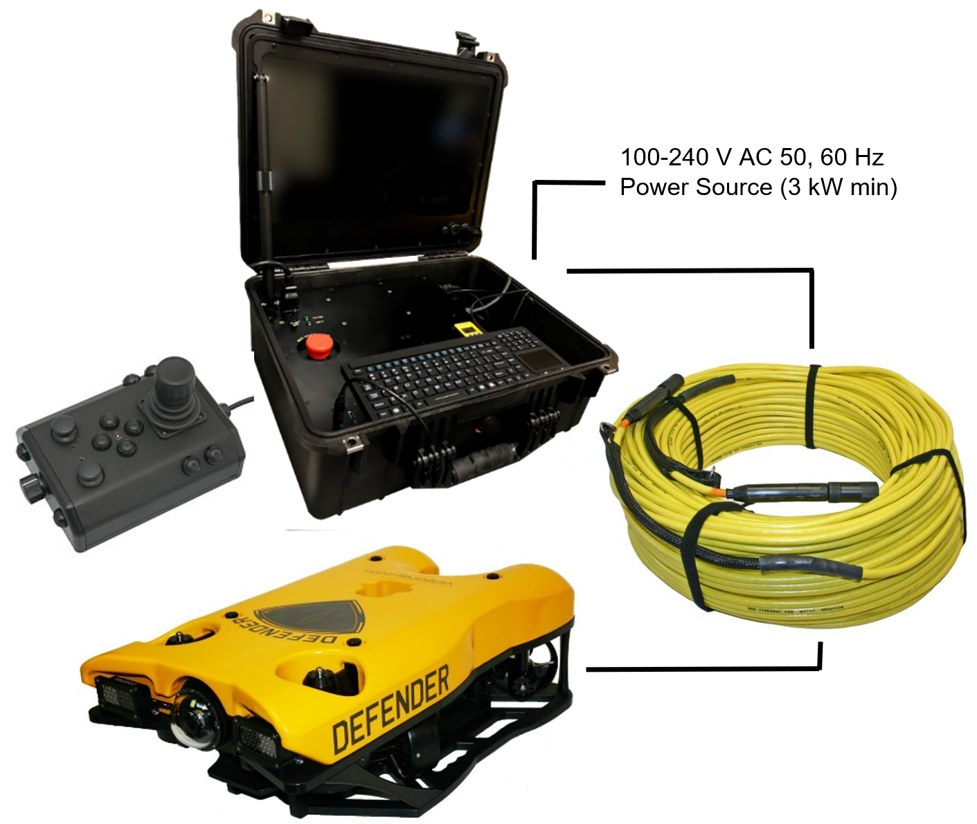
Introduction to the System ComponentsUnpack the system and familiarize yourself with the components.
Additional ItemsAdditional items may be supplied with your system including tools, spare parts and other items. If included, these items are described in other sections of this documentation. Some items shown may be optional and not included with your configuration. |
Pre-Dive Preparations
The pre-dive preparations consist of five parts:
Conduct a Visual InspectionAssuming this is your first time using the VideoRay, everything should be in proper working order and ready to go, but it is good practice to perform a pre-dive inspection before every dive, even your first. If any problems are noticed, they should be addressed before continuing.
Make the ConnectionsIt is best to start making connections at the ROV and working your way to connecting the system to the power source.
Top View Side View Some of the cables have been connected at the factory. See the appropriate sections of the Equipment Guide for detailed information about each of the connections. You will typically need to connect only the ROV, tether, strain relief hand controller, and power cord.
Power On Tests
The VideoRay MSS includes two circuit safety components.
Testing the Circuit Safety ComponentsConnect the power cord to a suitable power source. The GFCI can be found inline in the power cord.
Power On and LIM TestsSet the Power switch to the On position. The green Power On indicator light should turn on. If the green Power On indicator light is not on, make sure the system is connected to a working power source and the GFCI switch is turned on. Twist the ROV Power switch to the On position. The green 400 V Power On indicator light should turn on. If the green 400 V Power On indicator light is not on, make sure the system is connected to a working power source and the GFCI and main power switches are turned on. Test the LIM. The LIM can be found on the right side of the Operator Control Console. The GFCI switch and the main and 400 V Power switches must both be set to On in order to perform this test.
Starting the VideoRay Control SoftwareMake sure the system is connected to a working power source and the GFCI / Circuit Breaker and Power switches are turned on.
See the Software Guide for more information about the VideoRay control software. Testing the System's FunctionsThe next step is to ensure that the essential features of the ROV are functioning properly. Use the hand controller to perform the following tests. The manipulator functions listed below do not necessarily represent the full capabilities of the system. See the Hand Controller section of the Equipment Guide for the complete list of functions and more information about using the hand controller.
Test the thrusters
Test the lights
Test the camera functions
Good AdviceThe time to catch small problems before they become big problems is during the pre-dive inspection. |
Dive OperationsAfter the previous four pre-dive checks and tests have been completed successfully, you are almost ready to commence the dive. But, there is one more issue to address that could affect the performance of the ROV. The ROV is designed to be operated in a near neutrally buoyant configuration, so the last step before launching your VideoRay is to check the buoyancy, and adjust the ballast if necessary. For most operations, the buoyancy is optimal when the top of the float block is even with the water surface and the ROV is level. If the ROV is too buoyant or too heavy, the vertical position may be hard to maintain or control.
Buoyancy Check and AdjustmentTo determine if the buoyancy is correct, lower the ROV and at least 3 meters (10 feet) of tether into the water. You can lower the ROV by the tether - it will not hurt the tether because there is Kevlar in it. Observe the ROV in the water - it should not be floating too high or sink. It should also be floating level and not tipped to one side or pitched up or down. If the ROV floats too high, you will need to add some ballast weights. If the ROV sinks, you will need to remove some ballast weights. If the ROV is not floating level, you can change the locations of the weights. The buoyancy can be adjusted by adding or removing the supplied ballast weights to the vehicle. The weights can be added to or removed from the slots by hand. For most operations, the weights should be evenly distributed to provide a balanced attitude of the ROV in water. Commence the DiveOnce the buoyancy has been adjusted the ROV is ready to launch. Lower it into the water and operate the controls to maneuver it. The ROV can be lowered using the tether.
For your first dives, practice until you are comfortable operating the controls without looking at them and you are able to control the ROV with some precision.
Automated Flight OperationsAutomated flight operations require additional configuration and tuning to ensure accurate flight dynamics and control. See the Automated Flight Operations section for more details. Practice Makes PerfectDeveloping the skills to operate your Mission Specialist Pro 5 |
Post-Dive OperationsAt the conclusion of your dive, retrieve the VideoRay and power down the system by closing VideoRay Balefire software, turning off the ROV power switch, shutting down the computer and then turning off the main power switch.. Make sure the ROV is secure before disconnecting the tether. After disconnecting the tether, keep the tether connectors clean and do not let them drag on the ground. Proper maintenance of your VideoRay system ensures a long service life and that it will be ready to operate when you are. After each dive, you should visually inspect the system for damage that might have occurred during your operation.
DebriefingCongratulations! You are well on your way to becoming an accomplished micro-ROV operator, but there are still many things to learn and skills to master. Continue learning about the system by reviewing the additional sections of this documentation and, most importantly, practice, practice, practice. If you encountered any difficulties or have any questions, review these Quick Start Instructions and the other documentation that came with your system, including the Equipment Guide. If you still have difficulty or questions, contact VideoRay. Your success is our success, and we are here to help you get the most out of your VideoRay.
Ready to Learn More?To accelerate your learning and receive recognition for your knowledge and skills, VideoRay offers in-person classes and online training as well as the Micro-ROV User Certificate program. Training can be delivered at your site and customized to your needs. To learn more about these opportunities, click on the training link above to visit the VideoRay Educational Resources website. |
Specifications for the ROV ModulesSpecifications for the VideoRay M5 Modules are provided on the following pages. |
Power Module SpecificationsDepth Rating
Mechanical
Connections
Power Input
Power Output
|
Communications Module SpecificationsDepth Rating
Mechanical
Connections
Power Input
Power Output
Communications
Sensor Feedback
M5 Communications Module features and specifications are subject to change without notice. |
AHRS Module SpecificationsDepth Rating
Mechanical
Connections Power Input
Communications
Sensor Feedback
IMU Features
M5 AHRS Module features and specifications are subject to change without notice. |
Thruster Module SpecificationsDepth Rating
Mechanical
Connections
Power Input
Communications
Sensor Feedback
Features
M5 Thruster Module features and specifications are subject to change without notice. |
Camera Module SpecificationsDepth Rating
Mechanical
Connections Power Input
Communications
Sensor Feedback
Protocols
Visibility Features
M5 HD Camera Module features and specifications are subject to change without notice. |
LED Light Module SpecificationsDepth Rating
Mechanical
Connections
Power Input
Communications
Sensor Feedback
Features
M5 LED Light Module features and specifications are subject to change without notice. |
Specifications for the ROV AccessoriesSpecifications for the VideoRay Mission Specialist Defender accessories can be found on the respective information pages of each accessory. See the Optional Accessories section for more information. |
Tether SpecificationsTether Diameter
New tether was introduced in 2018. These tethers include a braided Kevlar around the conductors, are slightly different diameter and can be identified by an "FB" code printed on the tether.
Minimum Tether Bend Radius
Tether Connector Pin Configuration
Tether pin numbering in the connector is shown above. When looking at the mating surface of the connector, Pin 1 is the offset pin / socket. For male connectors, pins 2-8 proceed in a clockwise direction. For female connectors, sockets 2-8 proceed in a counter-clockwise direction. Tether Pin Function and Conductor Wire Gauge
Tether BuoyancyPerformance and Neutral tether includes buoyancy compensating foam that provides near neutral buoyancy in fresh water. Negative tether contains no foam and will sink. The connectors do not contain any buoyancy compensation and will sink slightly. Tether StrengthAll tether types include Kevlar that is rated at 450 kg (1,000 pounds), the connectors are rated 80 kg (175 pounds). The maximum usable tether length is limited by the ability of the tether to transmit power and data signals. The maximum usable tether length of MSS systems is about 550 meters (1,800 feet). MSS systems can use fiber tether to extend the range. See the Tether Management section of the Operations Guide for more information. Kevlar is a registered trademark of E. I. du Pont de Nemours and Company |
|
|
Mission Specialist Pro 5 Operator's Manual, 1.00.00 |
System Voltage AdvisoryAC InputInput voltage is universal at 100-240 VAC; 50, 60 Hz. The power requirement for the Mission Specialist operating at full power settings is 3,000 Watts. A 2,000 Watt source (i.e. generator) can be used if the system will not be used at full power settings. ROV DC PowerHistorically, the tether voltage to power the ROV has been increasing. Economy models (including the Scout, Explorer and Voyager), Pro 3 variants and the Pro 4 Ultra use 48 V DC for vehicle power. The Pro 4 uses 74 V DC. Mission Specialist systems uses 400 V DC with plans to use higher voltages in the future. Systems with voltages higher than 48 V DC include a LIM (Line Insulation Monitor) protection module in the ROV DC circuit.
VideoRay Negative, Neutral and PPT tethers are rated to 600 V DC and are safe to use on any system through the Mission Specialist 400 V DC.
The new version of the extended TDS is available that includes a 600 V rated slip ring. If you have any questions about system voltage and compatibility, contact VideoRay Support. |
|
|
Mission Specialist Pro 5 Operator's Manual, 1.00.00 |
Equipment GuideUnderstanding the features and capabilities of the Mission Specialist equipment is essential to get the most value out of using the system. The sections within this Equipment Guide provide details about each of the components. Topics in this Section |
|
|
Mission Specialist Pro 5 Operator's Manual, 1.00.00 |
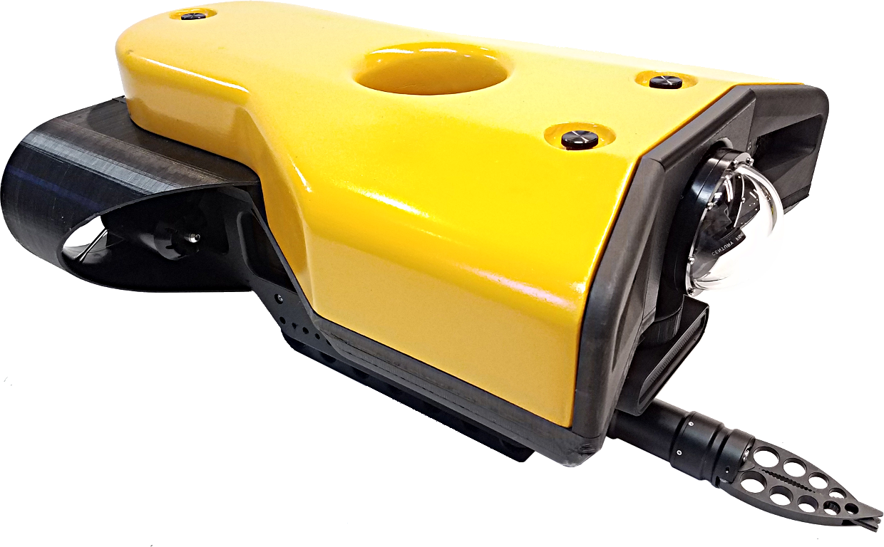
ROVThe Mission Specialist ROV consists of modular components (thrusters, lights, cameras, sensors) and a custom frame. Each Mission Specialist vehicle is designed to meet the requirements of a specific underwater mission. The frame and sensor payload can be optimized to deliver the vehicle to its intended destination and accomplish the tasks, whether that be recording video, taking measurements of various parameters, or navigation and remote sensing such as sonar or laser imaging.
The sections that follow provide information about the frame and modular components. |
ROV NomenclatureROV nomenclature follows the general pattern for seagoing vessels. The image below provides a visual reference for the directions and attitude relative to the ROV.  ROV Orientation and Directions ReferenceBow - The front of the ROV. Stern - The rear of the ROV Port - The left side of the ROV when facing forward. Starboard - The right side of the ROV when facing forward. Fore - Towards the front or The forward direction. Aft - Towards the rear of the rearward direction. Surface - To ascend or move up in the water column to a shallower depth. Dive - To descend or move down in the water column to a deeper depth. ROV Attitude and Motion ReferenceSurge - Forward and Reverse motion of the ROV, forward is positive. Heave - Up and Down motion of the ROV, up is positive. Sway - Left (to port) and Right (to starboard) lateral motion of the ROV, left is positive. Yaw - Right (to starboard) and Left (to port) rotational motion of the ROV, right (clockwise, viewed from the top) is positive. Pitch - Bow Up or Bow Down inclination of the ROV, bow up (clockwise, viewed from the port side) is positive. Roll - Port UP or Port Down relative to Starboard, port up (clockwise, viewed from the rear) is positive.
|
Power / Communications ModuleThe Power Module receives power from the topside and converts it to power levels required by the various modules, sensors and accessories.
8 Pin Male Tether Connector
5 Pin Female High Power (Thruster, Lights) Connector (2)
Power is rated at 750 Watts per port for 1,500 Watts total. Power Module ArrangementThe communications module is the "brains" of the vehicle and coordinates vehicle control systems and provides data paths for sensors and accessories. 9 Pin Female Interface Connectors
Power is rated at 300 Watts for the 24 Volt circuit and 120 Watts for the 12 Volt circuit. This is the total output of the internal DC/DC converters and is divided across all connections as demanded by each externally connected device. Each connector pin is rated to 5 Amps, which should not be exceeded. For any one connector, the maximum Watts should not exceed 120 Watts for the 24 Volt circuit and 60 Watts for the 12 Volt circuit. Communications Module Arrangement
Defaults: Group ID - 193; Node ID - 2; IP address - 192.168.1.64; RS-485 accessible |
AHRS ModuleAHRS - Attitude and Heading Reference System The AHRS is also sometimes referred to as an Inertial Measurement Unit, or IMU. It provides feedback on the vehicle's orientation. Measurements include magnetic heading, attitude and rates of change. The AHRS also includes a pressure sensor to determine the depth of the vehicle.
Cable Pinout
The Pro 5 vehicle AHRSD is mounted in the top center of the ROV frame.
|
Thruster ModuleMission Specialist vehicles use a modular thruster configuration that allows vehicle designs to be optimized for water conditions and payload delivery requirements. Modular thrusters are also easy to replace in the field.
Thruster PropellerThe propellers are designed to be used on counter-rotating thruster arrangements to eliminate torque roll or yaw. Propellers are identified by their pitch orientation using left and right based on their pitch. The convex edge of the propeller blade is the leading edge during motion that is considered forward for that thruster.
Cable PinoutThe Thruster connector uses a male / female stackable connector allowing the thrusters and LED lights to be connected in series.
The Pro 5 vehicle is a Defender frame that uses a vectored horizontal thruster arrangement, and three vertical thrusters. The thrusters are configured as shown below:
|
Camera ModuleThe camera module provides a live video feed from the vehicle to the surface.
Cable Pinout
High Definition Camera
|
LED Light ModuleThe LED Light Module provides variable levels of illumination and beam pattern control.
Cable PinoutThe LED Light connector uses a male / female stackable connector allowing the LED lights and thrusters to be connected in series.
|
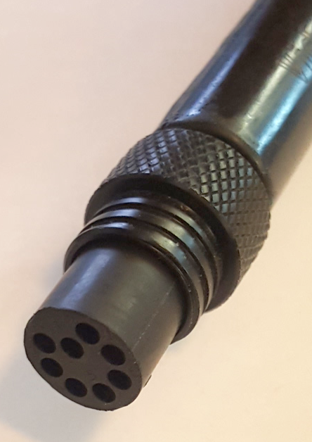
ROV ConnectionsThe Mission Specialist ROV system uses 3 types of connectors for power and communications between the control panel, vehicle modules and accessories. 8 Pin Tether Connector
Pin numbering starts at 1 for the offset pin and is clockwise on the male connector and counter clockwise on the female connector. 5 Pin Thrusters and Lights Connector
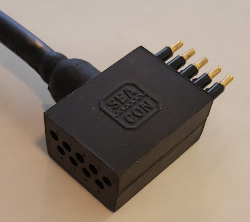
Pin numbering is clockwise starting at 1 in the upper left when looking at the face of the male connector with the row of 3 pins on top. 9 Pin Accessory Connector
Pin numbering is clockwise starting at 1 in the upper left when looking at the face of the male connector with the row of 5 pins on top. ROV Connections |
|
|
Mission Specialist Pro 5 Operator's Manual, 1.00.00 |
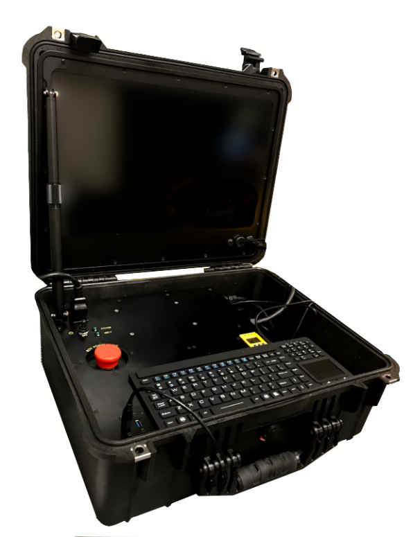
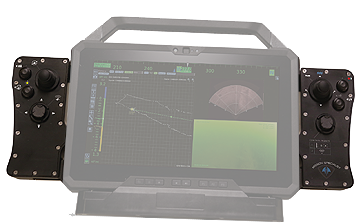
Workhorse Operator Control ConsoleThe Operator Control Console provides power, communications and a video interface between the surface and the ROV through the tether. The computer, which runs software to control the ROV, is housed in the Operator Control Console along with a display monitor .
Operator Control Console Power SpecificationsThe VideoRay MSS operates on typical residential power in the range of 100-240 Volts AC, 50,60 Hz. This can be provided from the land-based grid, a generator, or a battery with an inverter (optional). The typical power requirements for operating from a generator or inverter are 3,000 Watts continuous minimum. The system includes a GFCI (Ground Fault Circuit Interrupter) / Circuit Breaker to protect the operator. The power in the tether is 400 Volts DC. This circuit is protected by a LIM (Line Insulation Monitor). The procedures for testing the circuit safety components can be found in the Pre-Dive Preparations section of the Quick Start Instructions.
Display Monitor Tilt ArmThe Display Monitor Tilt Arm on the left side of the Operator Control Console can be used to adjust the angle of the Operator Control Console lid and monitor. To adjust the angle of the monitor, loosen the locking collar, adjust the lid to the desired angle and tighten the locking collar.
|
Safety CircuitsThe Operator Control Console includes three safety circuit components.
GFCI (Ground Fault Circuit Interrupter)The GFCI protects the operator from shock from the AC circuit of the power source. The GFCI is inline with the power cord. When initially connected to a power source, it is in the Off state. You must press the Reset Button to enable it. When enabled, the green LED will be illuminated.
LIM (Line Insulation Monitor)The LIM protects the operator and persons in the water nearby from shock from the DC circuit of the tether. While the GFCI switches are part of the GFCI component and must be turned on to operate the Operator Control Console, the LIM is automatically enabled when the system is turned on. The LIM operates on a principle similar to the GFCI and monitors the quality of the insulation of the conductors in the tether. If the resistance between the conductors drops below the safe threshold, the LIM will trip. A normal reading on the LIM display is > 4 M-Ohm, indicating that the insulation of the power conductors in the tether is good. If there is any degradation of insulation, the value displayed will decrease. The MSS LIM is two stage. When the LIM detects the resistance between the ROV power conductors falls below 900 kOhms, the yellow LIM Alarm A1 LED will turn on, but the power circuit will remain on. When the LIM detects the resistance falls below 200 kOhms, the yellow LIM Alarm A2 LED will turn on and the ROV power circuit will be disabled. The LIM can be reset by pressing and holding the R button. The yellow LIM Alarm light should turn off. To test the LIM, press and hold the T button. If the LIM continues to trip, the system should be inspected for a fault before being used. The LIM has additional features that are described in more detail in the LIM Module Manual. ROV Power Safety InterlockThe ROV Power Safety Interlock prevents the ROV power from being engaged unless an ROV is plugged into the tether. This feature protects users from accidentally contacting the ROV power circuit of an open tether connector. See the Operator Control Console Switches and Connections section for more information about these components and their locations, and see the Pre-Dive Preparations section of the Quick Start Instructions for information about testing these components. |
Workhorse Switches and Connections
The Operator Control Console top includes the following switches:
The Operator Control Console top includes the following connections:
The Operator Control Console side includes the following switches:
The Operator Control Console side includes the following connections:
|
ComputerThe computer provides the hardware and operating system platform for VideoRay ROV control software and image and video editing and production. The computer is embedded in the Operator Control Console.
The computer includes the following connections (which are passed through to connectors on the Operator Control Console):
Additional SpecificationsOperating System
Temperature
Power Input
Hard Disk Space
|
HD Monitor
The monitor includes a brightness knob. The monitor includes the following connections:
Additional SpecificationsSize
Power Input
Native Resolution
Brightness
Features
|
|
|
Mission Specialist Pro 5 Operator's Manual, 1.00.00 |
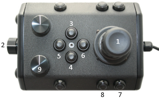
Hand ControllerThe hand controller is used to operate the VideoRay and its features. Several types of hand controllers are supported. Controllers not included in your configuration are available from VideoRay for purchase. Supported controllers include:
The hand controller functions are described in more detail in the following pages of this guide. Hand Controller CompatibilityAny Microsoft® Windows® compatible game controller can be used with the Mission Specialist, but each controller requires a configuration file to map the joystick, buttons and knobs to the ROV functions. Microsoft is a registered trademark of Microsoft. Windows is a registered trademark of Microsoft. |
Forward / Reverse ControlThe joystick is used to control the forward / reverse motion of the ROV. Location
UseDisplace the joystick forward (away from you) to move the ROV forward. Displace the joystick rearward (toward you) to move the ROV backward. The greater the displacement from the center position, the faster the ROV will move or turn in that direction. The joystick can be moved in any direction to simultaneously move forward or backward while turning or moving laterally.
Forward / Reverse Control |
Yaw ControlThe joystick is used to control the yaw motion of the ROV. Location
UseRotate the Joystick to the left to turn (yaw) the ROV to its left. Rotate the Joystick to the right to turn (yaw) the ROV to its right. Displace the Joystick to the left to slide the ROV to its left. Displace the Joystick to the right to slide the ROV to its right. The greater the displacement from the center position, the faster it will move or turn in that direction. The joystick can be moved in any direction to simultaneously turn while moving forward/backward or laterally.
Yaw Control |
Depth ControlThe Depth Control knob is used to make the ROV dive or surface by controlling the direction and amount of vertical thrust. Knob Location and Label
UseRotate the Depth Control knob forward (counterclockwise) to dive. The greater the rotation from the center position, the faster it will dive. Rotate the Depth Control knob backward (clockwise) to surface. The greater the rotation from the center position, the faster it will surface.
|
Lights IntensityThe Lights knob controls the intensity of the lights. Control Location and Labels
UseRotate the Lights Intensity knob counter clockwise to dim the Lights and clockwise to increase the intensity of the lights.
Lights Intensity |
Camera Tilt UpThe Camera Tilt Up button increases the vertical angle of the front camera in the upward direction. Button Locations and Labels
UsePress and hold the Tilt Up button to tilt the front camera up. Release the button when the camera has tilted to the desired setting or has reached the end of its range.
Camera Tilt Up |
Camera Tilt DownThe Camera Tilt Up button increases the vertical angle of the front camera in the downward direction. Button Locations and Labels
UsePress and hold the Tilt Down button to tilt the front camera down. Release the button when the camera has tilted to the desired setting or has reached the end of its range.
Camera Tilt Down |
Camera Focus InThe Camera Focus In button adjusts the focus of the front camera for near objects. Button Location and Label
UsePress and hold the Camera Focus In button to adjust the camera focus for near objects. Release the button when the camera has focused to the desired setting or has reached the end of its range. Camera Focus In |
Camera Focus OutThe Camera Focus Out button adjusts the focus of the front camera for far objects. Button Location and Label
UsePress and hold the Camera Focus Out button to adjust the camera focus for far objects. Release the button when the camera has focused to the desired setting or has reached the end of its range. Camera Focus Out |
SnapshotThe Snapshot button saves a still image from the active camera. Button Location and Label
UsePress the Snapshot button to capture a still image from the active camera. Snapshots are saved as .JPG formatted files in the gss_logs folder. They are automatically named by date and time. For more information, see the Snapshots section of the Operations Guide.
|
Video RecordThe Video Record button toggles the video record feature for the active camera. Button Location and Label
UsePress the Video Record button to start recording a video from the active camera. Press the Video Record button again to stop recording a video from the active camera. When the recording is active, the record icon button is illuminated green. Video Recordings are saved as .MP4 formatted files in the gss_logs folder. They are automatically named by date and time. For more information, see the Video Recording section of the Operations Guide
|
Cycle DisplayThe Cycle Display button cycles through the display modes of the control software. Button Location and Label
UsePress the Cycle Display button to switch the display modes of the control software. Display modes include:
Cycle Display Mode |
Manipulator OpenThe Manipulator Open button opens the jaws of the manipulator. Button Locations and Labels
UsePress and hold the Manipulator Open button to open the jaws of the manipulator. Release the button when the manipulator jaws open the desired amount or have reached the end of their range.
Manipulator Open |
Manipulator CloseThe Manipulator Close button closes the jaws of the manipulator. Button Locations and Labels
UsePress and hold the Manipulator Close button to close the jaws of the manipulator. Release the button when the manipulator jaws close the desired amount or have reached the end of their range.
Manipulator Close |
Manipulator RotateThe Manipulator Rotate knob rotates the jaws of the manipulator. Button Locations and Labels
UseRotate the Manipulator Rotate knob clockwise to rotate the manipulator jaws clockwise (when viewed from the rear of the manipulator). Rotate the Manipulator Rotate knob counterclockwise to rotate the manipulator jaws counterclockwise (when viewed from the rear of the manipulator). Center the Manipulator Rotate knob to stop the manipulator jaws from rotating. Manipulator Rotate |
|
|
Mission Specialist Pro 5 Operator's Manual, 1.00.00 |
Tether
Tether connects the ROV to the surface and provides power, communications, video and an APIC (Auxiliary Pair of Independent Conductors) for accessory use. The tether consists of conductors, a Kevlar® strength member, flotation (for Neutral and Performance tethers) and an outer jacket. It is available three types: Negative, Neutral and Performance (often called PPT), and can be purchased in standard and custom lengths. Neutral and Performance are neutrally buoyant in fresh water because they have a specially designed foam jacket. While larger conductors provide the best power transmission capacity, they lead to thicker tethers, which results in higher drag. Negative tether has the largest conductors (best power transmission capacity), followed by Neutral, and then Performance. Negative and Performance tether have the smallest diameter (least drag), while Neutral tether has the largest diameter. The tether connectors are wet mateable and can be connected while they are wet. One of the pins in the connector is offset. To connect the tether to the ROV, control panel or another tether, align the offset pin of the connectors and press the two connectors together until the base surface of each connector are touching each other. Then, connect the tether locking sleeves by screwing them together to secure the connection.Multiple tethers can be connected in series like conventional power extension cords. See the Tether Management section of the Operations Guide for recommended tether configurations.
|
Tether SpecificationsTether Diameter
New tether was introduced in 2018. These tethers include a braided Kevlar around the conductors, are slightly different diameter and can be identified by an "FB" code printed on the tether.
Minimum Tether Bend Radius
Tether Connector Pin Configuration
Tether pin numbering in the connector is shown above. When looking at the mating surface of the connector, Pin 1 is the offset pin / socket. For male connectors, pins 2-8 proceed in a clockwise direction. For female connectors, sockets 2-8 proceed in a counter-clockwise direction. Tether Pin Function and Conductor Wire Gauge
Tether BuoyancyPerformance and Neutral tether includes buoyancy compensating foam that provides near neutral buoyancy in fresh water. Negative tether contains no foam and will sink. The connectors do not contain any buoyancy compensation and will sink slightly. Tether StrengthAll tether types include Kevlar that is rated at 450 kg (1,000 pounds), the connectors are rated 80 kg (175 pounds). The maximum usable tether length is limited by the ability of the tether to transmit power and data signals. The maximum usable tether length of MSS systems is about 550 meters (1,800 feet). MSS systems can use fiber tether to extend the range. See the Tether Management section of the Operations Guide for more information. Kevlar is a registered trademark of E. I. du Pont de Nemours and Company |
Tether Strain ReliefThe Pro 5 strain relief is used to secure the ROV to the tether to prevent separation and loss of the vehicle if the tether connection becomes separated. The strain relief also minimized the load on the tether connector. There are two different strain relief systems. One is for use between the ROV and tether and the second is for use when connecting two tethers together. There is not a strain relief system for the topside connection. Instructions for using these strain relief systems is found on the following pages. |
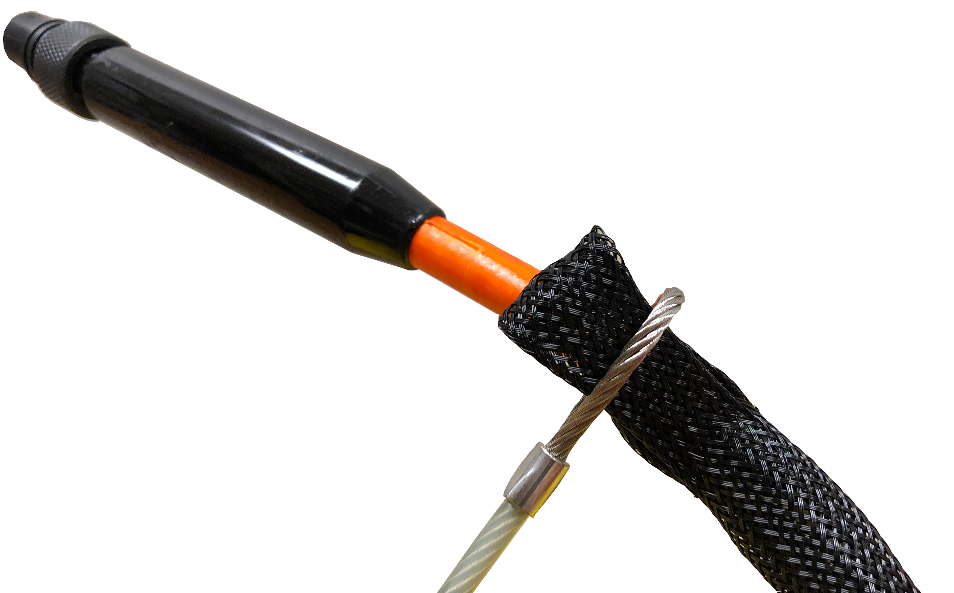
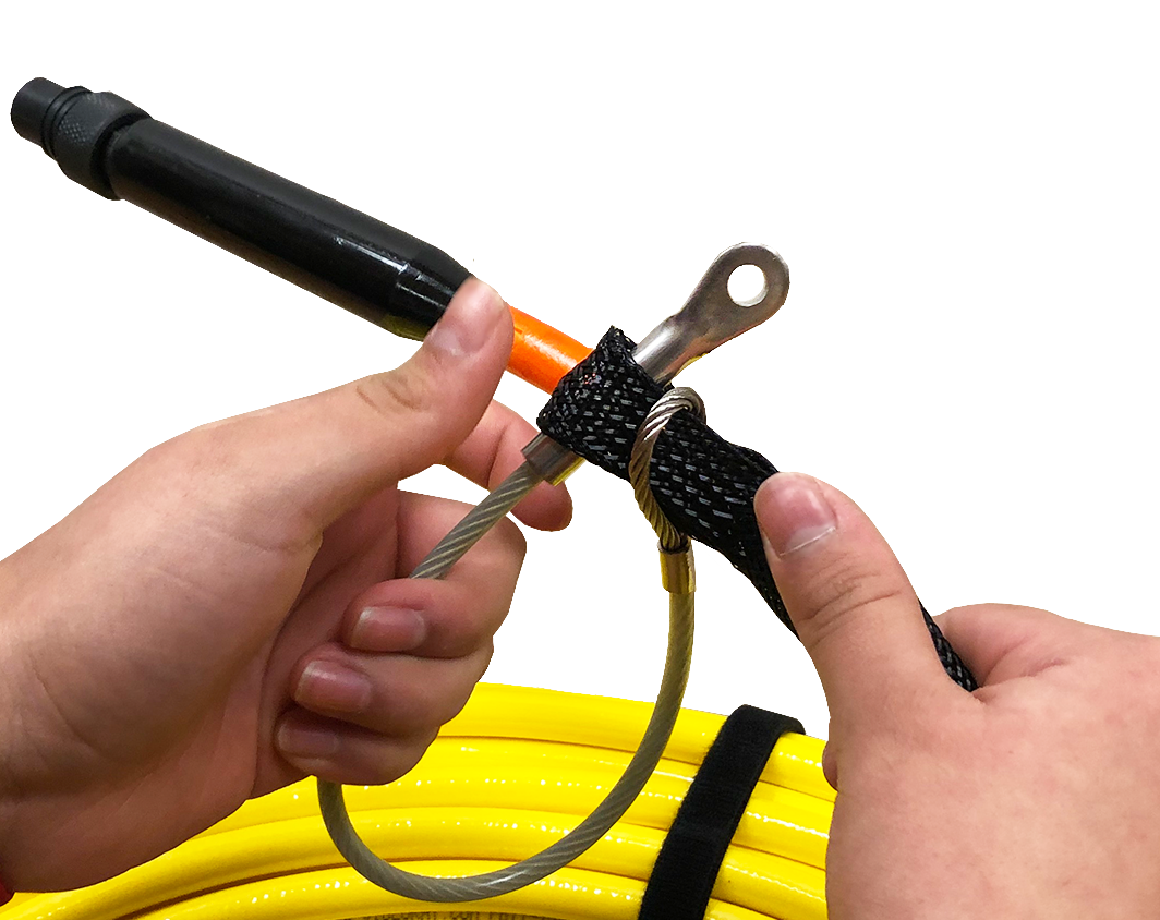
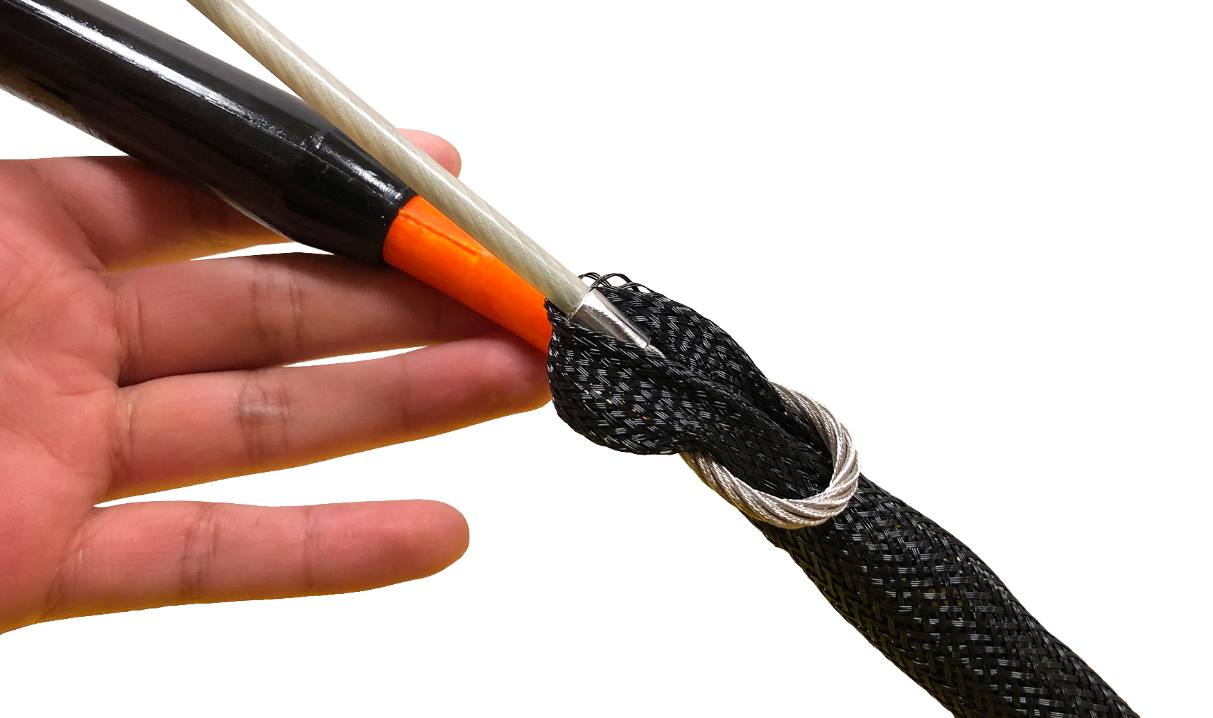
ROV to Tether Strain ReliefUse the following procedures to install and secure the vehicle to the tether to prevent loss of the vehicle due to a connection failure. The strain relief cable may already be attached to the tether. If so, you can skip steps 1 to 3.
|
Tether to Tether Strain ReliefWhen connecting multiple tethers for an operation, each connection should be secured with a tether to tether strain relief to prevent separation of the connection. Use the following procedures to install and secure the strain relief cord for tether to tether connections. The ROV strain relief cable may already be attached to the tether. If so, it should be removed.
|
|
|
Mission Specialist Pro 5 Operator's Manual, 1.00.00 |
Connections Summary
The following connections are required:
|
|
|
Mission Specialist Pro 5 Operator's Manual, 1.00.00 |
AccessoriesNumerous accessories can be used with the MSS to extend its capabilities and range of performance. These accessories allow the MSS to support a wider variety of mission profiles. This section provides an overview of what accessory equipment is available. For up-to-date information, including new accessories and updates, visit http://www.videoray.com. For information about installing and using accessories, including operational recommendations, please see the guides provided with each accessory. Accessory Types
Accessory Categories
Accessory Sources
Accessory UseMultiple accessories can be connected in parallel by the use of a stackable connector. The manipulator and cutter do not use a stackable connector, but can be used with other accessories by plugging in their connector as the last one in sequence.
|
Included AccessoriesSeveral topside accessories are included with all Mission Specialist system configurations. Sun ShadeThe sun shade can be attached directly to the control panel lid and provides shade for the computer and monitor to make it easier to see the displays when working in bright light. See the label on the sun shade for installation instructions. Tool KitA basic tool kit is provided in order to perform routine maintenance and field repairs. The tool kit also contains some spare parts including ballast weights, propellers and other items. Additional Sensors and ToolingThis configuration includes the following sensors and tooling: |
Optional AccessoriesThe following pages provide information about the various accessories that are supported on the VideoRay Defender. Your configuration may or may not include all of these accessories. |
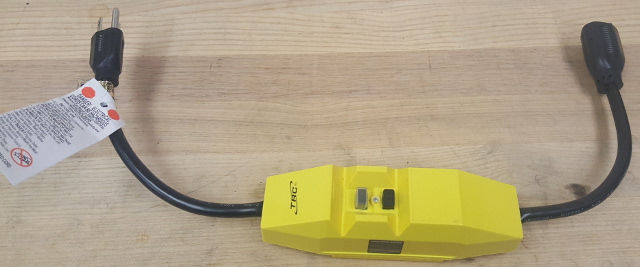
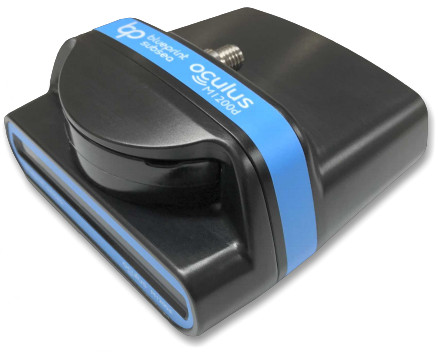
Blueprint Oculus Sonar 750DThe Blueprint Oculus Sonar 750D is a general purpose dual-frequency sonar used for navigation and high resolution imagery of near field target identification. For more information on the Oculus 750D sonar see the Datasheet and User Manual For operation of the Sonar within the Greensea software, see page 39 in the Greensea EOD Workspace Manual
|
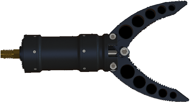
Rotating Manipulator
For operation of the manipulator, see the section about the hand controller. |
Mission Support AccessoriesIn addition to the equipment that is included with each MSS configuration and the commercially available accessories, VideoRay recommends users procure a variety of mission support items. The list of recommended items will vary depending on the typical mission requirements, although it will be obvious that some of these items have general applicability to all mission profiles. These brief lists are intended to provide a sample and stimulate thinking about what you might want to add to your "operations kit:" General Logistical Support
Tactical Operations Support
|
|
|
Mission Specialist Pro 5 Operator's Manual, 1.00.00 |
Software GuideMission Specialist software consists of three main components:
The topside Operator interface software is available in several versions:
|
|
|
Mission Specialist Pro 5 Operator's Manual, 1.00.00 |
Greensea User Manuals for the DefenderGreensea control software comes in three versions:
|
|
|
Mission Specialist Pro 5 Operator's Manual, 1.00.00 |
VideoRay Interface OverviewThere are four applications that are required to operate the VideoRay vehicle control software. These are stored in the ~/Flighthack folder.
Each application may be started in any sequence, but following a consistent sequence such as above is recommended. |
|
|
Mission Specialist Pro 5 Operator's Manual, 1.00.00 |
Software ManagementThis section provides information about the software environment and managing the software. |
Folder StructureHome/ - User Root Folder charts/ - Recommended location for charts firmware/ - Module Firmware flighthack/ - Mission Specialist Utilities gss_config/ - Configuration Files gss_logs/ - Recordings gss_mission/ - Mission Definition Files |
Software UpdatesSoftware updates can be downloaded from https://videoray.exavault.com/ Username: quarterdeck
The new version should be installed and ready to run. Contact VideoRay support if you need assistance. |
|
|
Mission Specialist Pro 5 Operator's Manual, 1.00.00 |
Module ConfigurationThe modular concept requires that modules be configured prior to installation or replacement in a specific vehicle arrangement.
Conceptual OverviewThrusters and other modules can be thought of as employees, and the vehicle as the jobsite. Each employee (Module) has a unique name (Serial Number stamped or printed on the module and coded in the firmware). When the employee goes to work at the jobsite (is installed on the vehicle), it is assigned an employee number (Node ID) by the person doing the configuration. The jobsite supervisor (control software) communicates with the employees using their employee number, so the employee number for each module on a jobsite must be unique. Work instructions are announced to all employees at the same time, so each employee must listen for their specific instructions and ignore the instructions for other employees. When there are multiple employees of the same type on a jobsite, these employees may be assigned specific work tasks (Application ID or Motor ID). The employee will only listen for instructions related to their work task. For example a starboard thruster will only respond to horizontal control inputs, while a vertical thruster will only respond to vertical control inputs. This approach allows vehicles to be configured with great flexibility. Examples include:
General Requirements
The following sections provide information about module replacement. |
Configuration CommandsThe following configuration commands are available for updating firmware and configuring M5 modules for MSS vehicle systems:
More information about using these commands can be found in the following section of this guide. |
Command: vr_refreshThe vr_refresh command is used to update the firmware on a module. Usevr_refresh [OPTIONS] [SINGLE_HEX_FILE_NAME]
|
Updating FirmwareFirmware can be found locally in the Home/firmware/ folder. The most up-to-date firmware is available from VideoRay's FTP server. You can download the firmware to the local folder by connecting to the Internet and using the following command:
Example firmware update commands for different modules are shown below. In each case, X.Y.Z should be replaced by the actual version number. Each vr_refresh command should be entered on one line. Ignore any line breaks that may appear in the vr_refresh commands displayed below. Power Module
Communications Module
AHRS Module
Thruster Module (Use the correct Node ID)
Camera Module
LED Module (Use the correct Node ID)
Firmware Block Sizes
|
Command: vr_enumThe vr_enum command is used to enumerate (list) the modules that are connected to the vehicle. Usevr_enum [OPTIONS] [min explcit id] [max explicit id]
Examples
For Power, Communications, Thrusters and LEDs
For the AHRS and camera modules, you need to include the virtual port. AHRS Module
Camera Module
|
Command: vr_setidThe vr_setid command is used to set the Node_ID and Group_ID of a module. Usevr_setid [OPTIONS] SN Node_ID Group_ID
Examples
For the examples below, replace "S.N" with the actual serial number. The serial number is case sensitive. Power Module
Communications Module
AHRS Module
Thruster Module (Use the correct Serial Number and Node ID)
Camera Module
LED Module (Use the correct Serial Number and Node ID)
|
Command: vr_debug_putty.pyThe vr_debug_putty.py command is used to configure or test a module. Use./vr_debug_putty.py [OPTIONS] [N [N...]]
Power Module
Communications Module
AHRS Module
Thruster Module (Use the correct Node ID)
Camera Module
LED Module (Use the correct Node ID)
|
Command: vr_create_virtport_all.shThe vr_create_virtport_all.sh command is used to create virtual ports that allow the Ethernet protocol to be used to communication with modules connected to the communications module. Virtual PortsMSS communications are supported using Ethernet and RS-485 protocols. Modules may use one protocol or the other, or both. The configuration commands described on the previous page, including vr_enum, vr_setid, vr_refresh and vr_debug_putty.py use only the RS-485 protocol. For modules that only support Ethernet, a virtual port must be set up to bridge the RS-485 to Ethernet for the Communications Module port to which the device is attached. The vr_create_virtport_all.sh can be used to create the required virtual ports. Use./vr_create_virtport_all.sh & There are no arguments for this command.
Example Using Virtual Ports to Communicate with a CameraThis example assumes that a Camera Module with serial number CAMADP000123 is plugged into port 2 of the Communications Module.
|
ROV Materials ListThe following is a list of materials used in the vehicle: Open this document in new Window Users may check this list against chemical compatibility charts available from several sources. This information is provided for convenience. Providing this information does not explicitly or implicitly extend the warranty to cover the use of VideoRay products in solutions that are not specifically listed in the Environmental Compatibility section. VideoRay is not responsible for errors or omissions in any of the presented information.VideoRay can provide engineering services for a fee to determine chemical compatibility. Contact VideoRay for more information. |
|
|
Mission Specialist Pro 5 Operator's Manual, 1.00.00 |
Project ManagementWhile the differences between conducting a recreational dive, an inspection of an offshore well riser, and a drowning victim recovery are quite dramatic, each of these dive missions usually consist of the following phases:
Of course, how critical a successful outcome is deemed and how much lead time and how many resources are available will dictate how much effort can or will be afforded to each phase. The essential knowledge and skills required for a consistent ability to "get the job done" go well beyond just being able to set up and pilot an ROV. In this section, the following topics will be discussed to help broaden your understanding of the scope of practical ROV applications. |
|
|
Mission Specialist Pro 5 Operator's Manual, 1.00.00 |
Maintenance GuideThis section will describe the maintenance requirements and procedures for periodic or common maintenance requirements. It will not be detailed enough to be considered a component level repair manual, but will address component replacement of modular components. |
|
|
Mission Specialist Pro 5 Operator's Manual, 1.00.00 |
User Maintenance PolicyUser's are ultimately responsible for the safe operation and longevity of their VideoRay equipment by minimally following best practices outlined in the Operator's / Maintenance Manual, recognized industry standards and using common sense.
VideoRay also understands that logistics and other issues may make it difficult and costly to return the equipment to a Factory Authorized Service Center for completion of some of the simpler procedures. The following procedures are considered acceptable for the owners and lessees to complete without impact on the warranty. Note that cleaning components is a required condition for continued warranty protection and that failure to exercise reasonable care during these procedures may result in warranty claims being denied.
Instructions for performing these procedures are included in the Operator's / Maintenance Manual. Users who do not feel comfortable completing these procedures are invited to contact VideoRay for assistance.
|
|
|
Mission Specialist Pro 5 Operator's Manual, 1.00.00 |
Configuration / Calibration |
Compass CalibrationFor the best navigation performance, the compass should be calibrated in the following situations:
Step-by-Step Procedures
|
|
|
Mission Specialist Pro 5 Operator's Manual, 1.00.00 |
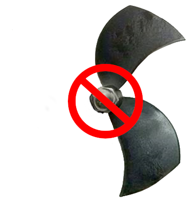
Propeller MaintenancePropellers are considered wear items and should be inspected before every dive during the Pre-Dive Setup procedures.
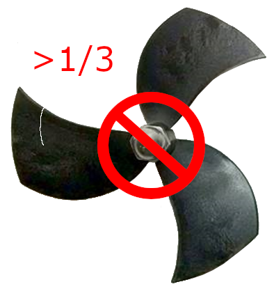
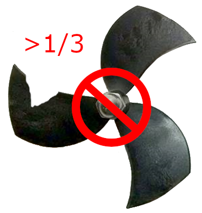
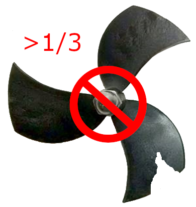
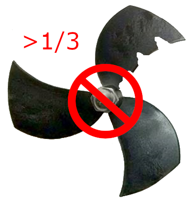
Propeller Replacement GuidelinesPropeller replacement can be based on a rigid pass/fail criteria, such as when a propeller blade breaks off and is missing, in which case the propeller should be replaced immediately, or based on a risk assessment when the propeller has mild to moderate wear. Such a risk assessment should consider the importance and urgency of the mission. If the mission is critical, deep or it would be difficult to retrieve the ROV in the event of a control failure due to the loss of a propeller, such as operating in a confined space, a propeller that exhibits even mild wear should probably be replaced. If the mission is brief, shallow and there is no risk of difficulty in retrieving the ROV by its tether, then even moderately worn propellers can remain in service. The following guidelines are provided to help determine whether propellers should be replaced or not. Propellers should be replaced if any of the following conditions are observed:
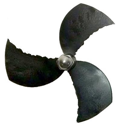
Generally Acceptable Propeller WearGenerally, any propeller that has a ragged edge can be used as long as it does not affect vehicle performance or control. Loose pieces or pieces bent out of the plane of the propeller should be removed using sandpaper or a file.
Propeller Replacement ProceduresPropellers are connected to the thruster shaft using a drill chuck-like collet that has a fluted tapered core that compresses on the shaft when the propeller nut is tightened.
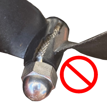
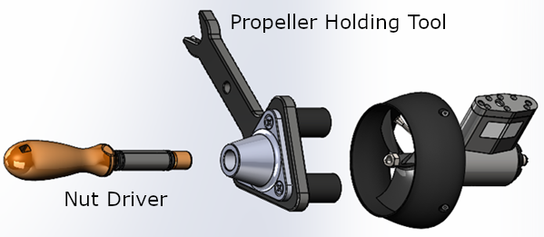
Propeller RemovalTo remove a propeller, loosen, but do not remove the nut using the propeller holding tool and 7/16" nut driver. The collet should then be free to slip out of the hub, open and release from the shaft. The propeller can then be pulled off the shaft.
If the propeller cannot be removed from the shaft, contact VideoRay Support for additional recommendations. Propeller Replacement
See the Thruster Arrangement configuration table for the correct propeller type selection for each thruster.
After selecting the correct propeller pitch for its installed location, loosen but do not remove the propeller nut and install the propeller on the thruster shaft until it is seated. Using the propeller holding tool and 7/16" nut driver, tight the propeller nut. The nut should be tightened as much as possible (assuming a person with average strength) to prevent it from slipping off during operations.
|
|
|
Mission Specialist Pro 5 Operator's Manual, 1.00.00 |
Module Configuration and Replacement |
Power Module ReplacementReplacing a Power Module requires hardware replacement. Currently, the Power Module will be pre-configured when delivered, so there is no need for software configuration procedures. Hardware ReplacementTo remove and replace a Power Module, follow these steps:
Power Module and Control Software ConfigurationThis section is reserved for future use. |
Communications Module ReplacementReplacing a Communications Module requires hardware replacement. Currently, the Communications Module will be pre-configured when delivered, so there is no need for software configuration procedures. Hardware ReplacementTo remove and replace a Communications Module, follow these steps:
Communications Module and Control Software ConfigurationRefer to the configuration parameter table in the Communications Module section of the Equipment Guide.:
|
AHRS ReplacementReplacing an AHRS requires hardware replacement. Currently, the AHRS will be pre-configured when delivered, so there is no need for software configuration procedures. Hardware ReplacementTo remove and replace an AHRS, follow these steps:
AHRS and Control Software ConfigurationThis section is reserved for future use. |
Thruster ReplacementReplacing a thruster requires both hardware replacement and software configuration procedures. Each thruster must be configured for its specific location on the vehicle. Configuration parameters are identified in the Thruster section of the Equipment Guide. Hardware ReplacementTo remove and replace a thruster, follow these steps:
Thruster and Control Software ConfigurationRefer to the configuration parameter table in the Thruster section of the Equipment Guide.:
|
Camera ReplacementReplacing a Camera requires hardware replacement. Currently, the Camera will be pre-configured when delivered, so there is no need for software configuration procedures. Hardware ReplacementTo remove and replace a Camera, follow these steps:
Camera and Control Software ConfigurationThis section is reserved for future use. |
LED Light ReplacementReplacing an LED Light requires both hardware replacement and software configuration procedures. Each LED Light must be configured for its specific location on the vehicle. Configuration parameters are identified in the LED Light section of the Equipment Guide. Hardware ReplacementTo remove and replace an LED Light, follow these steps:
LED Light and Control Software ConfigurationRefer to the configuration parameter table in the LED Light section of the Equipment Guide.:
|
This section contains a link to: ../../mss_manuals