Bootloader OperationThe bootloader runs on the module upon power up. The module will remain in the bootloader for 1 second waiting for a command to remain in the bootloader. If no command is received and the module has a valid application firmware loaded then the module will run the application firmware. If the "remain in bootloader" command is received or if there is no valid application firmware the module will remain in the bootloader.
Bootloader LED Blink PatternsThe bootloader blinks the module status LED to indicate its operational state.
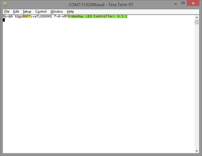
Typical blink startup pattern will be: 3 blinks, followed by 1 second of rapid blinks, followed by the application firmware blink pattern. If there is no valid application, the pattern will be 3 blinks, followed by continuous rapid blinks. Verification of Bootloader Operation via a TerminalThe bootloader emits an identifying message on startup. Part of the message is ASCII and thus human readable. This provides a method to insure that the bootloader is loaded on the module. Connect a terminal emulator (such as tera term or putty) to the serial port connected to the module. The terminal should be set to 115200, 8n1. Upon power up of the module the terminal will display the received characters. The display will look similar to the image below. If the text "BOOT" is visible then it is most likely that the bootloader is on the module.
ASCII terminal display showing bootloader message as well as text banner from a module application firmware (LED Controller). "BOOT" is highlighted in yellow, and the firmware message is highlighted in green. |
|
|
[ Help us improve this document ] [ Print this page |
M5 Communications Module
Operator's Manual
Operator's Manual


