Greensea Workspace Overview
Version:  A-1.00.00

Page 1 of 35
Greensea Workspace Software

Greensea Systems’ Workspace software is an easy-to-use, advanced autonomous vehicle control system for the VideoRay Defender. It provides exceptional stability and maneuverability for the vehicle even when performing the most complex tasks in the most challenging conditions. Multi-mode control means that operators can pass as much or as little responsibility on to the vehicle as the operation requires. Autonomous click-and-go, drag-and-follow and point-of-interest-relative navigation allow operators to focus on the task at hand, rather than on piloting the vehicle.

The Greensea control system combined with VideoRay’s innovative systems technology enables groundbreaking control capabilities for Mission Specialist Vehicles.

Greensea Workspace Overview
Version:  A-1.00.00

Page 2 of 35
Versions and Software Startup

Greensea control software is available in three versions:

  • EOD Workspace - made exclusively for military customers with more tightly controlled development cycles.
  • Professional Workspace - which parallels EOD Workspace, but is available for commercial use.
  • Basic Workspace - designed for systems without sensors that enable autonomous control. The corresponding features have been removed from the interface.

To start the software, simply double-click the desktop icon.

This lesson provides information that applies to EOD and Professional Workspaces. Any information that references autonomous navigation is not available in the Basic Workspace.

Greensea Workspace Overview
Version:  A-1.00.00

Page 3 of 35
Workspace Interface

The Greensea Workspace interface may look complicated at first, but we will break it down in this lesson. It is intuitive and flexible and can be optimally configured for the task at hand. There are eight primary elements of the interface, each providing specific feedback or accepting inputs.

In addition to the workspace interface, the operator can use the hand controller to command the vehicle with manual inputs.

Greensea Workspace Overview
Version:  A-1.00.00

Page 4 of 35
Control Bar

The first Workspace interface element is the Control Bar, which allows you to activate various control modes or command the vehicle to perform specific functions.

Greensea Workspace Overview
Version:  A-1.00.00

Page 5 of 35
Heading Instrument

The Heading Instrument uses a ribbon compass to display the vehicle's current heading.

Greensea Workspace Overview
Version:  A-1.00.00

Page 6 of 35
Depth Instrument

The Depth Instrument displays numeric and visual information about the vehicle's depth and altitude.

Note that the altitude requires the vehicle be equipped with an appropriate sensor, such as a DVL or an Altimeter.

Greensea Workspace Overview
Version:  A-1.00.00

Page 7 of 35
Map Window

The Map view provides a top down view of the vehicle's location. The map serves as the mission planning workspace and includes a variety of display control tools like zoom and pan.

Note that the location requires vehicle be equipped with an appropriate sensor, such as a DVL, ROV GPS or USBL.

Greensea Workspace Overview
Version:  A-1.00.00

Page 8 of 35
Map Control Tabs

The Map Control tabs are used to load and display overlay charts or maps, and reference the vehicle to its actual location in the world. Mission planning tools are also included in the Map Control tabs.

Greensea Workspace Overview
Version:  A-1.00.00

Page 9 of 35
Sonar Window

The Sonar view displays the sonar image, when the vehicle is equipped with sonar.

Greensea Workspace Overview
Version:  A-1.00.00

Page 10 of 35
Video Window

The Video view displays the video image from the ROV's camera.

Greensea Workspace Overview
Version:  A-1.00.00

Page 11 of 35
Camera / Sonar Control Tabs

The Camera / Sonar Control tabs can be used to make adjustments to the camera, lights, sonar and power and control sensitivity settings.

Greensea Workspace Overview
Version:  A-1.00.00

Page 12 of 35
View Selection

The Workspace default view includes all elements, including the Map, Sonar and Video views. You can configure the display to focus on a specific view using the F1 through F5 function keys.

  • F1 displays the Default view with all elements.
  • F2 displays the Video view at its maximum size.
  • F3 displays the Sonar view at its maximum size.
  • F4 displays the Map view at its maximum size.
  • F5 displays the Sonar and Video views stacked vertically.

Greensea Workspace Overview
Version:  A-1.00.00

Page 13 of 35
Control Bar Icons

Let's take a closer look at each of the interface elements starting with the Control Bar.

The Control Bar includes buttons to:

  • Record and take a snapshot.
  • Enable the Auto stability modes, including Auto Heading, Auto Depth or Auto Altitude, Auto Pitch, and Auto Roll.
  • Enable Dynamic Positioning.
  • Enable Orbit and Sonar Orbit modes.
  • Enable the Hold feature that can be used to pause a mission when the vehicle reaches the next waypoint.
  • Open the Jog Controls window.
  • Switch between Operator mode and Diagnostics mode.

When activated, the buttons change color from blue to green.

Note that Auto Depth and Auto Altitude cannot be selected at the same time.

Each of these modes will be discussed in more detail in upcoming lessons.

Greensea Workspace Overview
Version:  A-1.00.00

Page 14 of 35
Heading Instrument Use

The Heading Instrument uses a ribbon compass to display the vehicle’s current heading in the center of the instrument. The current heading is displayed in green text. If Auto Heading is on, the desired heading or set point is displayed in white text and a white arrow visually indicates the set point.

In addition to the heading, the vehicle’s current pitch and roll are displayed on the left in green text. When Auto Pitch and/or Auto Roll are enabled, the set points are displayed in white text.

There is an alarm panel on the right. When there are no active alarms, the alarm panel is hidden.

Greensea Workspace Overview
Version:  A-1.00.00

Page 15 of 35
Depth Instrument Use

The Depth Instrument displays the current depth of the vehicle on the scale and at the top of the scale in green text. If Auto Depth is on, the desired depth or set point is displayed in white text and a white arrow visually indicates the set point.

If available, the current altitude of the vehicle is displayed at the bottom of the scale in green. If Auto Altitude is on, the desired altitude or set point is displayed in white text and a white arrow visually indicates the set point.

The depth and altitude (if available) historical trends are displayed graphically as a series of dots.

At the top of the Depth Instrument, a Turns Counter displays how many turns the ROV has completed. Clockwise turns are positive, counterclockwise turns are negative. The Turns counter can be reset to zero during start up.

The Zero Depth button below the turns counter can be used while the vehicle is on the surface to calibrate the pressure sensor to ensure the depth is reading zero on the surface.

Greensea Workspace Overview
Version:  A-1.00.00

Page 16 of 35
Map Window Use

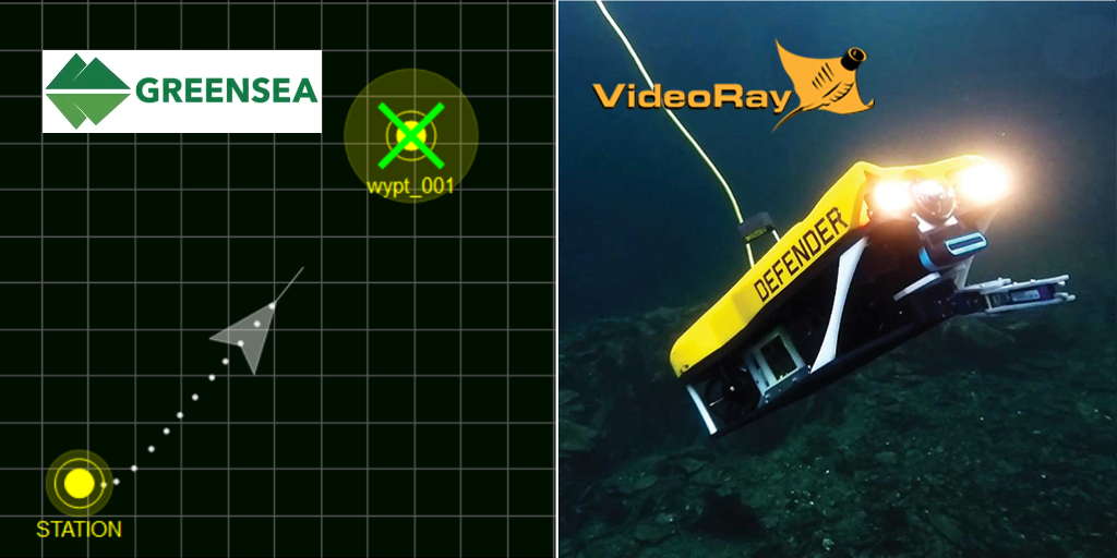
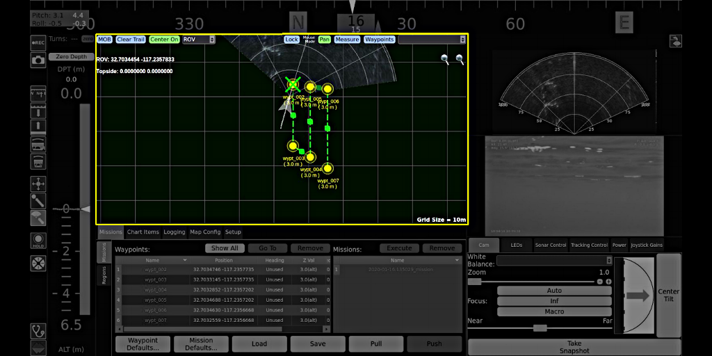
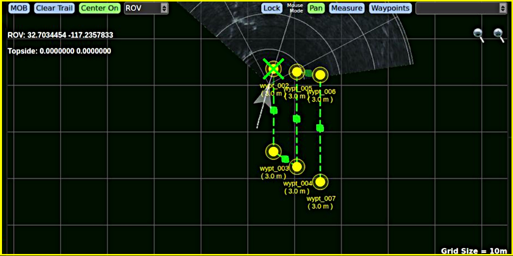
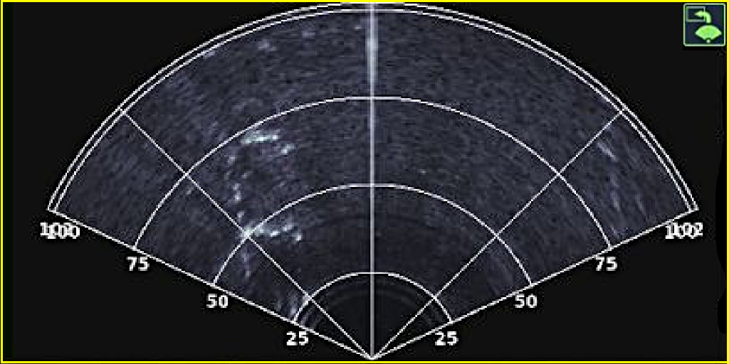
When equipped with appropriate sensors, the vehicle's geolocation can be updated in real-time on the map. The vehicle is displayed as an arrowhead indicating not only its location, but its heading as well. In addition to the vehicle, the sonar can be overlaid on the map providing geolocation of sonar targets.

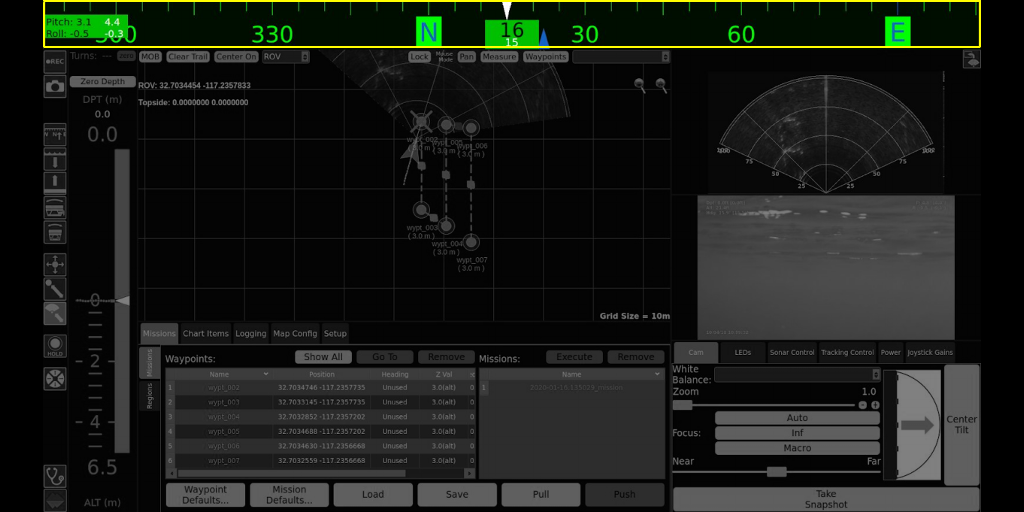
Map controls include pan and zoom, but the map cannot be rotated. Clicking and dragging the mouse on the map will pan the map. Zooming in and Out can be achieved by clicking on the zoom in or zoom out buttons, or by using the mouse's scroll wheel. While zooming, the map's scale is updated in the lower right.

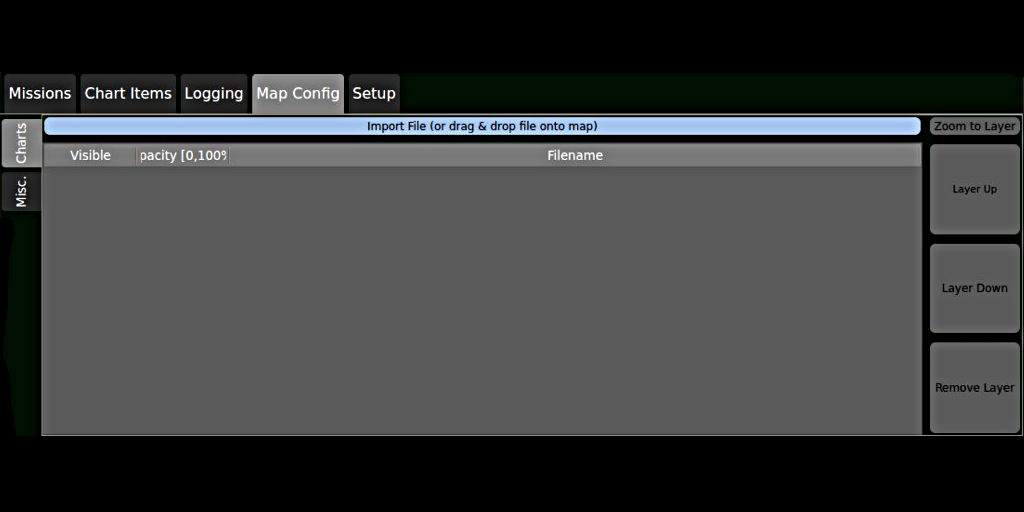
Bathymetric charts and maps or aerial photos can be superimposed on the map providing addition visual clues about the relative location of the vehicle.

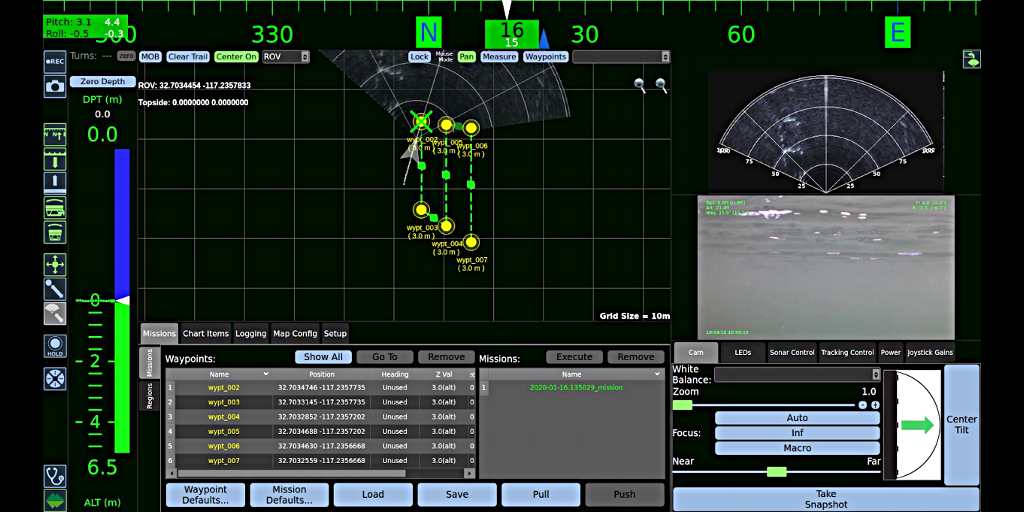
The Map can include a HUD (Heads Up Display) of the ROV and Topside coordinates and the coordinates of the mouse's location can also be reported in the HUD.

Across top of the map are several buttons. Starting at the left, they are:

  • MOB - Clicking this button places a Man Overboard point at the location of the ROV. It includes the heading, depth and attitude of the ROV when clicked, so the ROV can be navigated to the exact location and orientation.

  • Clear Trail - While the ROV is moving across the map, it leaves a breadcrumb trail of dots. Clicking this button clears the trail.

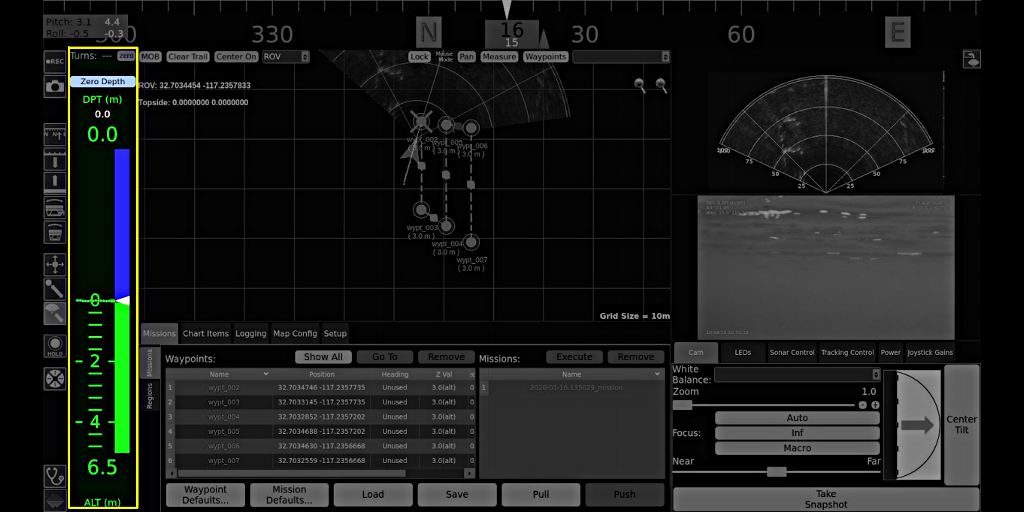
  • Center On - Clicking this button will move the ROV or Topside location to the center of the map area. The selection is determined by the pull-down list to the button's right.

  • Lock - Clicking this button locks the Waypoints and Markers that have been placed on the map so they cannot be accidentally moved while panning the map.

  • Pan / Measure / Waypoints - this radio button group sets the map mouse mode. When Pan is active, clicking and dragging the mouse pans the map. When Measure is active, clicking and dragging the mouse reports the bearing and distance from the first click to the mouse's current location. When Waypoints is active, clicking the Map will place a waypoint at the location of each click.

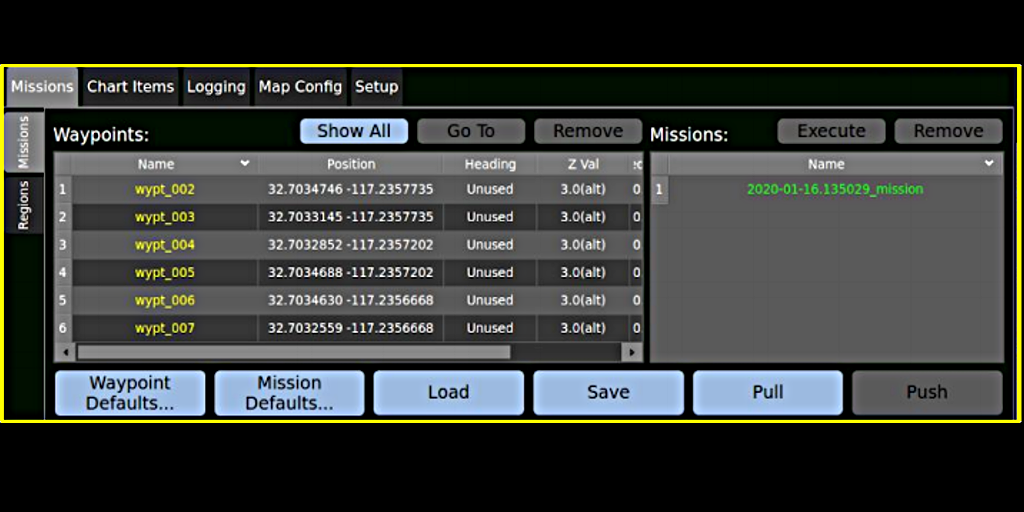
  • The pull-down selection list determines the mission to which waypoints will be added.

Operationally, you can interact with the map in several ways including commanding the vehicle to navigate to a selected location.

We will discuss these operational commands, waypoints, missions, and Lock button in more detail in upcoming lessons.

Greensea Workspace Overview
Version:  A-1.00.00

Page 17 of 35
Map Control Tabs Overivew

The Map Control tabs include data about missions, waypoints, markers, MOB (Man Overboard) points and other functions like adding charts to the map view or setting up the geolocation information.

The Map Control tabs can be selectively displayed or hidden. When hidden, more usable map space is available.

We will take a brief look at each tab, but there will be a lot more to learn about these tabs in upcoming lessons.

Greensea Workspace Overview
Version:  A-1.00.00

Page 18 of 35
Missions Tab

The Missions tab allows you to define and manage waypoints, missions and regions.

Greensea Workspace Overview
Version:  A-1.00.00

Page 19 of 35
Chart Items Tab

The Chart Items tab contains data for Markers and MOB points that have been placed.

Greensea Workspace Overview
Version:  A-1.00.00

Page 20 of 35
Logging Tab

The Logging tab allows you to specify the location where recordings will be stored, and manage playback and data export.

Greensea Workspace Overview
Version:  A-1.00.00

Page 21 of 35
Map Config Tab

The Map Config tab allows you to select charts and maps to display in the map view, and manage other configuration items like the system of units used and the HUD overlay text.

Greensea Workspace Overview
Version:  A-1.00.00

Page 22 of 35
Setup Tab

The Setup tab is used to define how the system uses georeferenced data from the vehicle's and topside sensors.

Greensea Workspace Overview
Version:  A-1.00.00

Page 23 of 35
Sonar Window Use

The sonar view is primarily a display only view. It includes an icon button in the upper right to overlay the sonar image on the map view when asked. The sonar settings can be changed in the sonar control tab, which we will discuss shortly.

Greensea Workspace Overview
Version:  A-1.00.00

Page 24 of 35
Video Window Use

The Video view is also a display only view. The video feed can also include video overlay text information, which can be selectively recorded or not independently from how it is displayed on the screen in this view.

Greensea Workspace Overview
Version:  A-1.00.00

Page 25 of 35
Video Text Overlay Use

Video Text Overlay is controlled in the diagnostic view. To access this view, click on the diagnostic stethoscope icon in the lower left of the screen. When the diagnostic view opens select the Vehicle Configuration tab at the top. The overlay controls are found at the bottom of this view.

Each overlay text item can be selectively displayed or not by clicking on its button. The overlay item is not displayed when the button is blue and will be displayed when the button is green. You can see on the left that there are separate "master" controls for the on screen display versus whether the text overlay is recorded or not.

There are three fields for user entered text, which, for example, could be a project name or crew names, weather conditions, etc. Even though these buttons have the specific names of, Dive #, Note 1 and Note 2, you can enter any text you desire in any of these fields.

When you have finished setting up the Video Overlay Text the way you like it, click on the Greensea Logo button in the bottom left of the screen to return to the operating mode view.

Greensea Workspace Overview
Version:  A-1.00.00

Page 26 of 35
Camera / Sonar Control Tabs Oveview

The Camera / Sonar control tabs controls the camera and sonar settings as expected, and they also control a few other items.

The Camera / Sonar controls tab can be selectively displayed or hidden by pressing the F6 key. The tabs cannot be displayed when the selected view is set to map only (F4).

We will take a brief look at each tab, but there will be a lot more to learn about these tabs in upcoming lessons.

Greensea Workspace Overview
Version:  A-1.00.00

Page 27 of 35
Camera Tab

The Cam, or Camera tab includes camera focus and zoom controls, white balance selection, a camera tilt indicator and buttons to take a high resolution snapshot or center the camera's tilt.

Greensea Workspace Overview
Version:  A-1.00.00

Page 28 of 35
LEDs Tab

The LEDs tab allows you to vary the light spread from narrow beam to wide beam and control the maximum allowable setting for each.

Greensea Workspace Overview
Version:  A-1.00.00

Page 29 of 35
Sonar Tab

The Sonar tab allows you to select the frequency (low for navigation and high for target identification), adjust the range and gain and control the color palette and other image quality settings.

Greensea Workspace Overview
Version:  A-1.00.00

Page 30 of 35
Tracking Control Tab

The Tracking Control tab allows you to control the sensitivity and threshold settings for sonar target tracking.

Greensea Workspace Overview
Version:  A-1.00.00

Page 31 of 35
Power Tab

The Power (Management) tab allows you to set the maximum power (in Watts) that the ROV will consume. This can be useful when working in high currents or when using long umbilical lengths.

Greensea Workspace Overview
Version:  A-1.00.00

Page 32 of 35
Joystick Gains Tab

The Joystick Gains tab allows you to set the joystick sensitivity for the vertical, horizontal and yaw or turns. Different pilots may prefer to work with different settings.

Greensea Workspace Overview
Version:  A-1.00.00

Page 33 of 35
Summary

This concludes our introductory tour of the Greensea Workspace Interface. Additional lessons will cover the operational aspects of using these features to control the ROV, plan missions, rely on the sensors for autonomous control and record and playback video and other data.