Mission Specialist Defender |
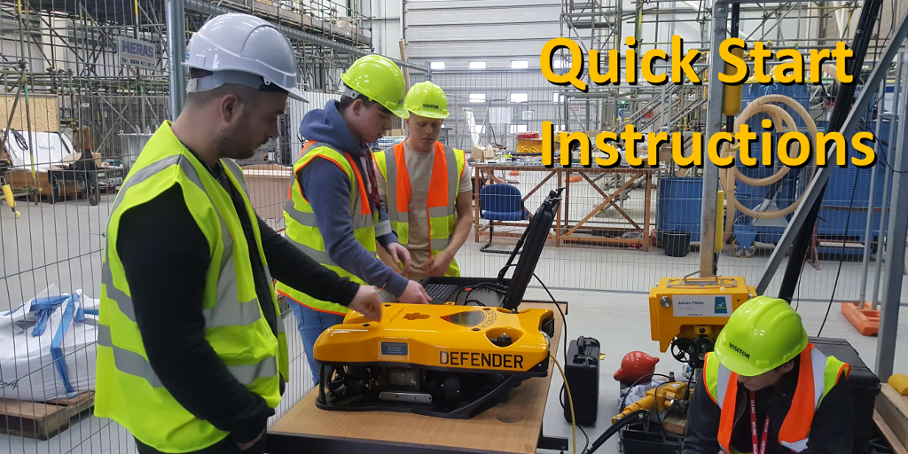
Quick Start Instructions |
|
These Quick Start Instructions serve two purposes. First, for the new user, they provide a guided tour, focusing on what you need to know about how to set up the system. It is the quickest way for a new user to get operational, and do it with some assurance they will not damage anything or hurt anyone. For experienced operators, it serves as a checklist to ensure consistent application of best practices on every dive. While this 8 step Quick Start guide is complete for its purposes, there are many more aspects of the system to learn, such as piloting skills, operating sensors and tooling, data collection and analysis, routine maintenance and field repair, and the list goes on. Some of these additional topics are available here in this library as Virtual Training Lessons, and all of the topics are available in the Operator Manuals. And, VideoRay's Support Team is always available to assist should you need us. |