Mission Specialist Defender
IP65 Hand Controller Mapping
Version:  A-1.00.00

Page 1 of 13
VideoRay IP65 Hand Controller

The VideoRay IP65 Hand Controller is used to control the vehicle functions such as the vehicle thrust, light intensity, camera, and accessory controls.

The Hand Controller is IP65 rated, meaning it is water and dust proof.

The orientation shown in the image above, with the joystick on the right side, is the correct way to hold the hand controller.

Operating the hand controller with the incorrect orientation can lead to incorrect vehicle commands.

The IP65 Hand Controller USB cable connection must be plugged into the User Control Console while in use.

Please note that only one Hand controller should be plugged into the system at a time.

Mission Specialist Defender
IP65 Hand Controller Mapping
Version:  A-1.00.00

Page 2 of 13
Horizontal Forward / Reverse

The joystick input shown in the image above, controls the vehicle forward and reverse thrust control.

The vehicle response is proportional to the hand controller joystick input. The greater the hand controller input, the greater the vehicle response will be.

The joystick will auto center when released, which will cease the corresponding action.

Mission Specialist Defender
IP65 Hand Controller Mapping
Version:  A-1.00.00

Page 3 of 13
Horizontal Yaw

The joystick input shown in the image above, controls the vehicle left and right yaw thrust control.

When in manual mode, the vehicle response is proportional to the hand controller joystick input. The greater the hand controller input, the greater the vehicle response will be. When in Autos mode, the hand controller joystick input controls the set point.

The joystick will auto center when released, which will cease the corresponding action.

Mission Specialist Defender
IP65 Hand Controller Mapping
Version:  A-1.00.00

Page 4 of 13
Horizontal Lateral

The joystick input shown in the image above, controls the vehicle left and right lateral thrust control.

The vehicle response is proportional to the hand controller joystick input. The greater the hand controller input, the greater the vehicle response will be.

The joystick will auto center when released, which will cease the corresponding action.

Mission Specialist Defender
IP65 Hand Controller Mapping
Version:  A-1.00.00

Page 5 of 13
Vertical Dive / Surface

The left knob input shown in the image above, controls the vehicle vertical control.

The pointed indicator knob helps display the specified input. When the indicator knob is pointed downward, the ROV dives and when the indicator knob is pointed upward the ROV surfaces. To zero the vertical indicator knob input, the knob must be centered.

The depth control knob has a center detent so that, by feel, the operator can tell when the knob is centered.

When in manual mode, the vehicle response is proportional to the hand controller depth knob input. The greater the hand controller input, the greater the vehicle response will be. When in Autos mode, the hand controller joystick input controls the set point.

Mission Specialist Defender
IP65 Hand Controller Mapping
Version:  A-1.00.00

Page 6 of 13
Pitch Control

The two buttons grouped furthest to the right in the image above, control the vehicle pitch. These buttons are labeled by a Defender ROV pitched upward, and one pitched downward.

Pitch control requires the auto mode to be activated.

In this group, the button on the right controls the ROV upward pitch, and button on the left controls the ROV downward pitch. Each press of the button controls in this group vary the ROV pitch by 5 degrees.

The button highlighted on the left side of the hand controller resets the ROV pitch and roll. This button is labeled using a level tool icon.

Mission Specialist Defender
IP65 Hand Controller Mapping
Version:  A-1.00.00

Page 7 of 13
Camera Controls

The four buttons grouped in the center of the hand controller, as shown in the image above, are used to control the ROV camera.

The buttons at the top and bottom of this group control the ROV camera upward and downward tilt. The upward camera tilt button is labeled with a camera icon and an arrow pointing upward. The downward camera tilt button is labeled with a camera icon and an arrow pointing downward.

The buttons on the left and right side of this group control the ROV camera near and far focus. The camera focus near button is labeled with a fish icon, and the camera focus far button is labeled with a mountain icon.

Holding any of the buttons down in this group will continue the action. For example, if the camera tilt up button is pressed and held down, the camera the will continue to move upward until the button is released, or until the camera reaches the end of its movement range.

Mission Specialist Defender
IP65 Hand Controller Mapping
Version:  A-1.00.00

Page 8 of 13
Lights Control

The knob highlighted in the bottom left corner of the hand controller image shown above controls the ROV LED module brightness. Turning the knob counter clockwise will dim the LEDs until they are completely turned off. Turning the knob clockwise will increase the brightness of the LEDs until the LEDs reach the maximum LED brightness level.

The maximum LED brightness level can be set in the 'LEDs' tab located in the Greensea software.

Mission Specialist Defender
IP65 Hand Controller Mapping
Version:  A-1.00.00

Page 9 of 13
Snapshot / Record

The snapshot button, highlighted in the top left corner of the hand controller image shown above, takes a full screen capture of the current software view.

The record button highlighted in the bottom left corner of the hand controller image shown above, toggles the record feature. Pressing the button once will start the recording and pressing the button again will stop the recording.

The recording status can be seen on the Greensea software control bar record icon. If actively recording, the record icon in the software will appear green and the word 'Logging' will appear at the top of the map view

.

Mission Specialist Defender
IP65 Hand Controller Mapping
Version:  A-1.00.00

Page 10 of 13
Manipulator

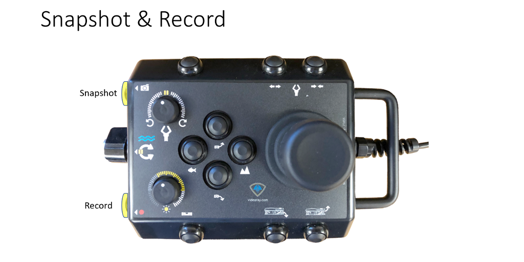
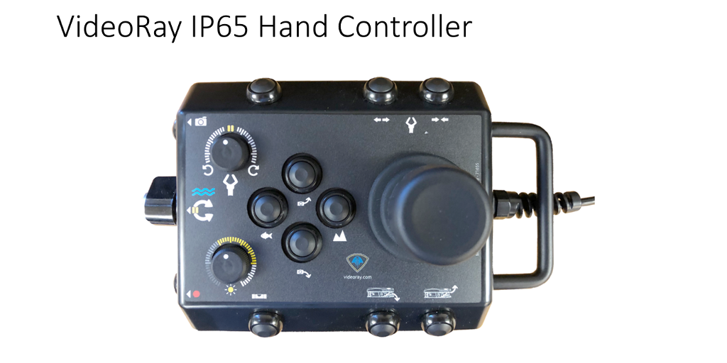
The knob located in the top left corner of the hand controller picture, controls the rotation on the rotating manipulator accessory.

When viewed from the rear of the manipulator, rotate the manipulator knob clockwise to rotate the manipulator jaws clockwise, and rotate the knob counterclockwise to rotate the manipulator jaws counterclockwise. Center the manipulator rotate knob to stop the manipulator jaws from rotating.

The two buttons highlighted in the top right corner of the hand controller image shown above, control the manipulator jaw open and close functions.

Press and hold the manipulator open button (labeled in the image above) to open the jaws of the manipulator. Release the button when the manipulator jaws open the desired amount or have reached the end of their range.

You should not continue to hold the manipulator open button when the jaws have reached the end of their range.

Press and hold the manipulator close button (labeled above) to close the jaws of the manipulator. Release the button when the manipulator jaws close the desired amount or have reached the end of their range.

You should not continue to hold the manipulator close button once the jaws have closed on an object or reached the end of their range.

When piloting the ROV, the pilot can use their middle or ring finger to open and close the manipulator while holding the joystick. By doing this, the pilot can maintain control of the vehicle wile actuating the manipulator.

Mission Specialist Defender
IP65 Hand Controller Mapping
Version:  A-1.00.00

Page 11 of 13
All Autos Off

The 'All Autos Off' button highlighted in the top left corner of the hand controller image above, disables all active auto modes and dynamic positioning.

It is good for a pilot to get in the habit of using the 'All Autos off' button when preparing to retrieve the vehicle.